A clear, accurate cable assembly drawing is essential for smooth manufacturing. Inaccurate details can cause miscommunication, faulty parts, delays, and extra costs. Precise drawings align designers, engineers, and production teams, ensuring the final product performs as intended.
This article covers everything you need to know about cable harness drawings, including use cases, key components, and best practices.
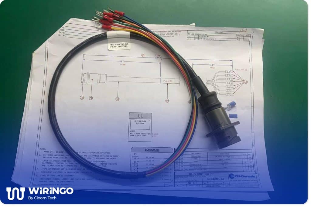
Caption: mil-spec cable assembly above its drawing
Get Your Free Sample!
Explore our custom services now. Email us at [email protected] for more details.
What is a Cable Assembly Drawing?
A cable assembly drawing is a detailed blueprint that shows exactly how wires, connectors, and other components should come together. Think of it as an instruction manual for cable assemblies. It covers wire colors, lengths, shielding, pinouts, and even how the cable should bend or route. Without the drawing, manufacturers are left to guess, increasing the risk of errors.
These drawings aren’t just sketches; they follow industry standards so everyone, from engineers to assemblers to QA teams, can read them the same way. A precise drawing means fewer mistakes and faster production for aerospace, medical devices, or industrial machinery.
Get Your Free Sample!
Explore our custom services now. Email us at [email protected] for more details.
When Do You Need a Cable Assembly Drawing?
Cable assembly drawings aren’t just paperwork. They’re the difference between a smooth project and costly surprises. Here’s where they matter most:
Prototype Cable Assemblies
Prototype cable assemblies are your first real-world test of a design. Before committing to full production, they help verify that everything fits, functions, and performs as expected. While these early versions don’t need to be perfect, they do need to be accurate enough to identify potential issues.
Many manufacturers use rapid prototyping techniques to speed up this phase. Things like 3D-printed connectors or temporary overmolds let engineers check dimensions and functionality quickly. The drawings for prototypes focus on the essentials—key lengths, connector types, and basic routing. This lean approach helps teams iterate faster while still gathering valuable data.
Production Cable Assemblies
When you’re ready for volume manufacturing, the stakes are higher. A production drawing is the guide to ensure every cable is built correctly.
The transition from prototype to production requires careful review. Teams need to confirm that the cable assembly design is functional and optimized for manufacturing. Small details make a big difference. Precise specifications help prevent costly mistakes when producing hundreds or thousands of units.
Unlike prototype drawings, production versions need to account for long-term consistency. They include everything necessary for repeatable results, from material specifications to quality checks. Any special handling or testing requirements should be documented to maintain standards throughout the production run.
Legacy System Repairs & Retrofits
When maintaining older equipment, off-the-shelf cable assemblies often won’t cut it. Machines with decades-old wiring or discontinued connectors need custom cable assembly solutions. A detailed drawing ensures replacement cables match the original specs down to the last millimeter.
Without a proper drawing, you’re guessing. Repair teams might improvise, which can lead to downtime or equipment damage. For example, a 1990s CNC machine may need a cable with precise bend radii to fit tight spaces. A drawing removes the guesswork, especially for rare or obsolete parts.
Safety-Critical Applications
In industries like medical devices and aerospace, cable assemblies must be fail-proof, not just functional. Drawings go beyond basic specs, including details like flame-retardant materials, strain relief points, and sterilization requirements.
Regulators often require these drawings for certification. For instance, a medical imaging system’s cable assemblies might need to withstand 10,000 flex cycles or resist specific chemicals. The drawing becomes a legal record that proves compliance. Missing one detail could cause delays or recalls for the entire project.

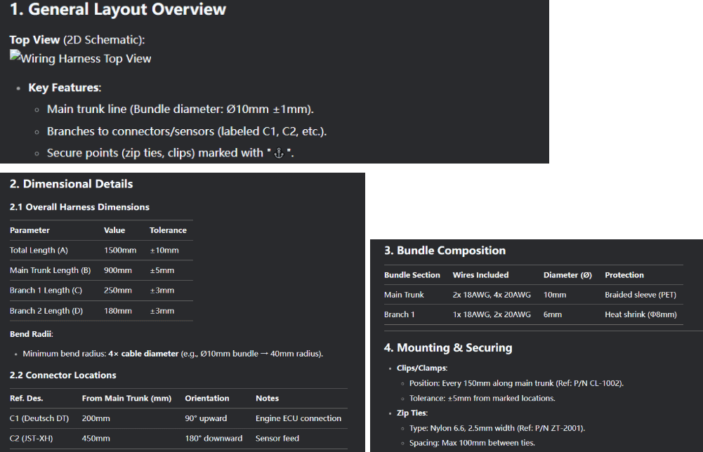
Caption: wiring harness on our step-by-step assembly sequence sheet
Key Components of a Cable Assembly Drawing
A complete cable assembly drawing combines visual representations with detailed specifications to eliminate ambiguity during production.
Physical Layout and Dimensions
The drawing must clearly define the cable’s physical characteristics, including:
- Overall length, including any service loops or extra length for installation flexibility
- Exact measurements for each branch and breakout point
- Minimum bend radius requirements to prevent conductor damage
- Connector placement and mating orientation
- Strain relief locations and mounting points
Multiple views (isometric, side, top) are often necessary for complex harnesses to show routing through equipment. Dimensioning should follow standard engineering practices with clear tolerance callouts.
Connector Pinouts and Wiring Details
This section provides the electrical roadmap:
- Comprehensive pin-to-wire mapping for every connection
- Wire specifications, including gauge, insulation type, and color coding
- Shielding requirements and grounding methods
- Polarization and keying features to prevent incorrect mating
- Special termination requirements (crimp, solder, etc.)
Best practices include both tabular data and graphical representations of connector layouts.

Bill of Materials (BOM)
The BOM serves as the parts list and procurement guide:
- Complete listing of all components with manufacturer part numbers
- Detailed wire specifications (conductor size, insulation material, etc.)
- Connector details, including shell material and plating
- Accessories like strain reliefs, grommets, and labels
- Approved alternate parts for supply chain flexibility

Assembly Instructions and Specifications
This critical section translates design to production:
- Step-by-step assembly sequence
- Termination specifications and tooling requirements
- Quality control checkpoints and inspection criteria
- Testing protocols (continuity, hipot, signal integrity)
- Compliance standards and certification requirements
- Packaging and labeling instructions
For mission-critical applications, additional documentation may include:
- Environmental ratings (temperature, chemical resistance)
- Flex cycle requirements for moving applications
- Maintenance and service life expectations
Proper documentation should allow any qualified manufacturer to produce identical assemblies that meet all design requirements. The level of detail should reflect the assembly’s complexity and the importance of its application.

7 Cable Assembly Drawing Best Practices
Creating effective cable assembly drawings requires attention to detail and alignment with industry standards. Here are seven best practices.
1. Include Proper Title and Version Tracking
Every professional cable assembly drawing must begin with a labeled title block containing essential identification information. This includes the project name, assembly number, revision index, preparation date, and the responsible engineer’s contact information. Next to the drawing, a detailed revision history table should track all changes. It should include columns for the revision ID, date, description of changes, and approval signatures.
2. Follow Standard Drawing Conventions
Effective cable assembly drawings rely on universally recognized symbols and notations to communicate clearly across teams and suppliers. Standardized symbols for components like D-sub connectors, coaxial interfaces, and terminal blocks should be drawn according to IEEE or IEC specifications to prevent misinterpretation. Consistent visual conventions are equally important: using the same line weights for conductors and outlines, maintaining uniform color coding, and applying identical labeling methods throughout the drawing. A comprehensive legend should be included to explain any unique symbols or abbreviations, particularly for custom components lacking industry-standard representations.
3. Specify Cable Details Completely
Comprehensive cable specifications form the technical foundation of any reliable assembly drawing. Beyond listing basic parameters like conductor gauge and length, the drawing should precisely define the conductor construction, insulation material, and exact wall thickness measurements. Electrical characteristics must include both voltage ratings and impedance values for high-frequency applications and maximum current capacity at different ambient temperatures. Environmental specifications should cover the operational temperature range, outdoor application UV resistance, and chemical compatibility requirements. For certified products, include all relevant standard markings (UL, CSA, MIL) with their specific certification numbers.
4. Cable Routing and Path Design
The drawing must clearly illustrate the cable pathway from origin to termination points. Use continuous lines for primary routes and dashed lines for secondary paths or optional runs. Show all penetration points through panels or bulkheads, indicating proper grommeting or sealing requirements.
For complex installations, include elevation markers for vertical routing and minimum bend radius indicators at direction changes. Use distinct line styles to differentiate between fixed segments (secured with clamps) and flexible sections (service loops).
5. Integrate Cable Management Solutions
Design for maintainability by specifying key management components: cable tray size and load capacity, tie-wrap anchor spacing, and drip loops at vertical-to-horizontal transitions. Show separation distances between power and signal cables to reduce interference. For harsh environments, include details for stainless steel braided sleeves or convoluted tubing, along with their attachment methods.
6. Incorporate Safety Information
Prominently display warning symbols and safety notes near relevant components: high-voltage flash warnings near power terminals, arc-fault cautions at disconnect points, and thermal risk indicators near heat-producing elements. Include a dedicated safety legend explaining all symbols used. Reference applicable safety standards (OSHA, NEC, IEC) with their specific article numbers for electrical clearances and protection requirements. Add biocompatibility or flammability class markings directly on the medical or aerospace applications drawing.
7. Implement Digital Documentation Practices
Create native CAD files (AutoCAD Electrical, SolidWorks Electrical) with proper layer organization for different cable types. Export to PDF with embedded 3D views and interactive bookmarks for key sections. Maintain a cloud-accessible version control system with permission-based access for different stakeholders. Include metadata fields for quick searching by project number, revision status, or component keywords. Generate mobile-optimized versions with zoomable details and offline access capability for field use.
Bring Your Drawings To Production
Whether testing a prototype, scaling production, or maintaining legacy equipment, the correct drawing ensures consistent, accurate builds. From standardized symbols to detailed specs, proper documentation ensures your design intent is clearly understood and reliably translated into assemblies that meet performance and industry standards.
At Wiringo, we specialize in this crucial translation from drawing to product. Our manufacturing team treats your documentation as the blueprint it is, delivering cable assemblies that meet every specification and providing practical insights to improve manufacturability and performance.

Hommer Zhao
Hommer Zhao serves as Director of Wiringo, leveraging a wealth of expertise in custom wire harness and cable assembly.
Drawing on more than a decade of hands-on expertise in the electronics field, Hommer focuses on wire harness manufacturing, custom cable assembly, and expedited restricted product production. His operations include a pair of wire harness production facilities and two dedicated PCB manufacturing & PCBA sites, all strategically located across Shijiazhuang, Shenzhen, Jiangmen, and the Philippines.
Hommer frequently refers to resources like Wiring Harness News for up-to-date insights and methods related to wire harness production.
Beyond his research and reading, Hommer also contributes to the Wiring Harness Manufacturer’s Association (WHMA), which offers invaluable resources and professional guidelines to wire harness specialists.
Get Your Free Sample!
Explore our custom services now. Email us at [email protected] for more details.