About Cat5 Cable Assembly, Although many people consider wireless connections simpler, some still prefer wired connections because of bandwidth on their home network, multimedia sharing, and wireless security risks.
Wired networks allow fast internet access, media streaming, file sharing, IP security cameras, online gaming, and another standard ethernet wiring.
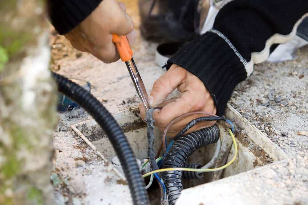
Cat5 cables are essential in modern homes today. You can transmit data to security cameras, HDMI devices, home networks, and telephones. Therefore, this article will discuss in detail how to assemble a Cat5 cable and breaks it down into a simple three-step process.
Cat5 Cable Assembly: What Are Cat 5 Cables?
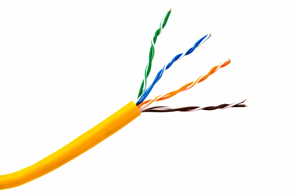
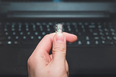
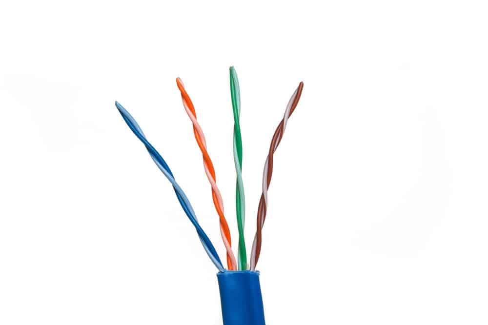
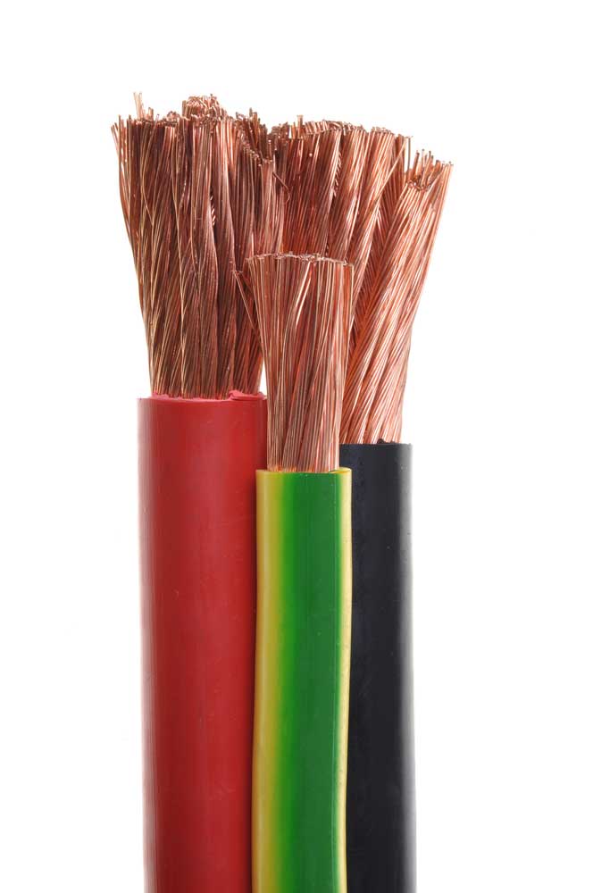
Often referred to as LAN or ethernet cables, Category 5 network cables comprise four pairs of twisted copper wires terminated by an RJ-45 connector.
The term category or cat has nothing to do with a cable’s transfer speed but simply describes the physical attributes. For instance, Cat5 and Cat5e cables fall under the same category because they share the same physical attributes, such as the number of pairs.
Additionally, the category refers to cables of the same frequency. Enhancements or variations often exist in the same category.
Cat5 cables are fifth-generation twisted pair ethernet cables. However, the number 5 indicates newer and more advanced manufacturing specifications than older versions. Therefore, the higher the number, the faster the transmission rate.
Cat 5 Cable Standard
The ANSI/TIA/EIA-568-A standard defines the specification of Cat5 cables. Also, you can use it to determine the specific performance requirements and test for frequencies of up to 100 MHz.
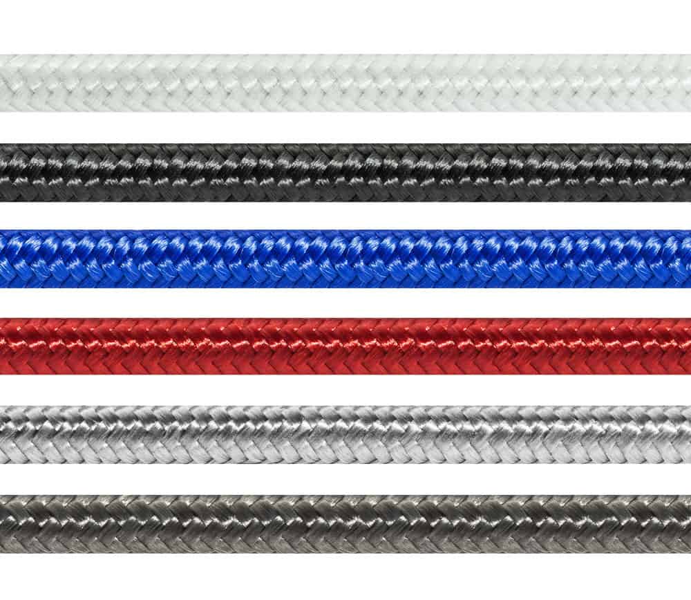
Cat5 cables come in both solid and stranded conductor forms. In addition, stranded conductor forms are more flexible and can withstand great bending without breaking. An example of stranded forms is patch cables. However, permanent wiring applied in structured cabling is solid core. To determine the type and category of a cable, check the cable jacket for any printed identifications.
Specifications indicate that Cat5 cables use pure copper conductors. However, the industry has had counterfeit cables made of copper-clad aluminum over time.
Today, Cat5 cables are a standard feature. They offer a bandwidth of up to 100 MHz and speeds of up to 100 Mbps, making them ideal for carrying ethernet, video, and telephone signals. The cable also features an unshielded twisted pair. Alternatively, you could opt for a screened twisted pair. UTP Cat5 cables have their wires twisted to reduce crosstalk and noise. But unlike STP Cat5 cables, UTP cables are unconfined to avoid interference.
Professionals recommend ensuring your Cat5 cable is a maximum of 100 meters long. If your cable is longer without the help of a bridge or network device, your network will face some challenges, such as data transmission speed degradation and packet loss.
Four pairs of twisted copper wires
Cat5 Cable Assembly: Cat5 Vs. Cat5e
Cat5e cables are an enhancement of Cat5 cables that were standard ratified in 1999. With that in mind, Cat5e cables offer improved performance compared to standard Cat5 cables. Also, they offer much faster speeds and increased ability to traverse distances without crosstalk impacting the signal.
These cables are 24-gauge twisted pair wires capable of supporting Gigabit networks over segment distances of up to 100 meters.
Also, Cat5e cables are more flexible, allowing them to bend further to fit in tight spaces.
Cable
Shielding
Type
Bandwidth
Max Speed
Characteristic Impedance
Main Difference
Cat5
Unshielded
UTP
100MHz
10/100 Mbps
100 ohms
Increased Crosstalk
Cat5e
Unshielded
UTP
100MHz
1000Mbps/1 Gbps
100 ohms
Minimum Crosstalk
Depending on the manufacturer, the cable cost varies. However, generally, Cat5e cables are more expensive than Cat5 cables.
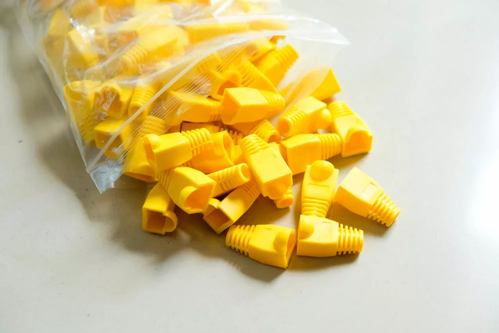
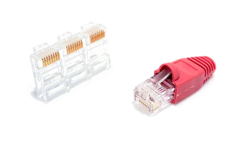
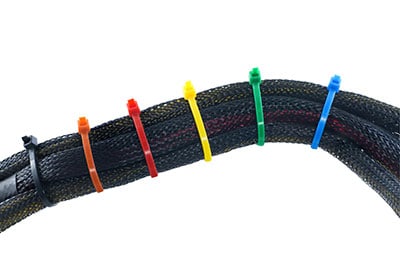
Caption: Cable Boots
Cat5 Cable Assembly: Cat 5 Color Code/Cat 5 Wiring Standard
As mentioned earlier, the ANSI/TIA-568 defines cable types, cabling topologies, and connector types. Often called RJ45 connectors, 8P8C modular connectors are commonly used to connect Cat5 cables. Therefore, for the connector, all eight wires in the modular connector have to be in a specific order. Otherwise, the cable won’t function.
There are two standards for the order of wires, T568A and T568B, with the cable being terminated in either scheme. However, both schemes function equally well and can be interchanged in an installation if both ends of the cable use the same scheme.
Below is a table on the color and arrangement of wires in Cat5 cable for every wiring standard.
T568A
RJ45 Pin Number
Wiring Color
1
White/Orange
2
Orange
3
White/Green
4
Blue
5
White/Blue
6
Green
7
White/Brown
8
Brown
T568B
RJ45 Pin Number
Wiring Color
1
White/Green
2
Green
3
White/Orange
4
Blue
5
White/Blue
6
Orange
7
White/Brown
8
Brown
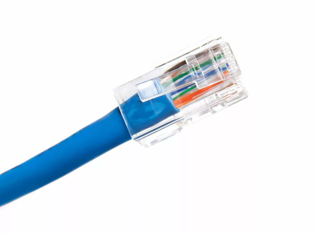
RJ 45 wiring
How To Make A Cat5e Or Cat5 Patch Cable
If you’re looking to learn how to make a Cat5 or Cat5e patch cable, you’ve come to the right place. Follow the steps below as a guide.
Step 1
This cable mainly applies to Cat5e RJ45 connectors.
Step 2
Cut the length of cable you need. If you’re planning on using Snagless boots, it’s best to slip them on now. Therefore, ensure the boots face outwards to the connector.
Step 3
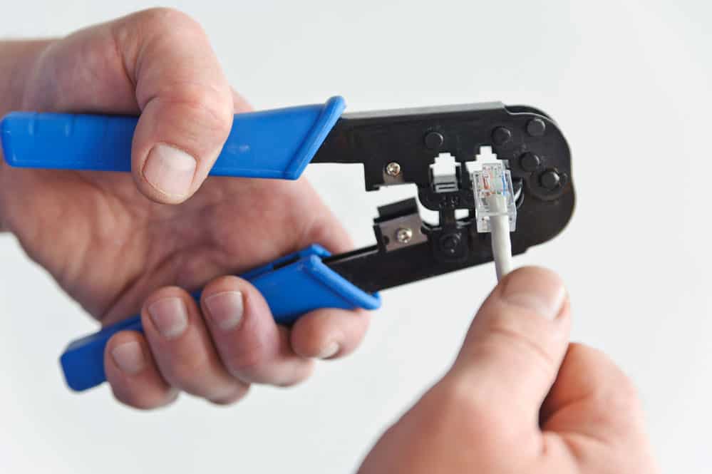
Next, strip back the jacket about an inch using the cutter in your crimping tools.
Alternatively, strip the cable by hand. Also, ensure precision to avoid nicking individual wires. Untwist all pairs, ensuring each wire is as straight as possible.
Step 4
The T568-B wiring scheme should work for a standard patch cable.
Step 5
Bunch all the wires closely together by holding them between your thumb and forefinger. Then proceed with cutting all the wires half an inch from the end of the jacket at a 900 angle from the cable. Using a sharp tool is best to avoid squashing the wire’s ends.
Step 6
Ensure the connector is facing up, then insert the wires into the connector. Exert some pressure on the wires to ensure they sit properly on the contacts in the connector.
Step 7
Inspect the connector’s tip to ensure all the wires are fully inserted. A useful tip is to ensure each wire end is fully visible, and there should be enough cable jackets in the connector to crimp against. Furthermore, for the ideal placement, you could slide the load bar slightly forward.
Step 8
Put the connector in the crimping tool and squeeze tightly.
Try to get a full swing from the handle for better results.
Step 9
Repeat the procedure on the other end with your desired wiring scheme. Also, ensure the boots fit snugly over the connectors when done.
Step 10
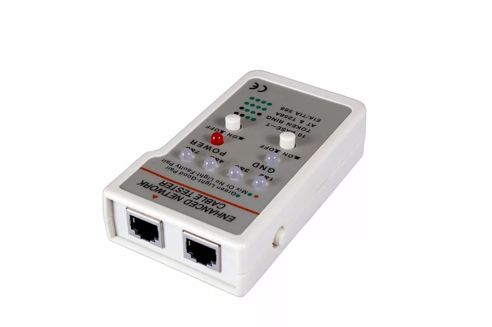
Check for opens, continuity, or shorts using a cable tester.
Caption: Cable Tester
Conclusion:
Undoubtedly, making patch cables is challenging, but over time, with frequent practice, you’ll get the hang of it. For any Cat5 cable assemblies, contact Cloom Tech for the best services. Our team of professionals is fully equipped and trained to handle all your projects.
Cat6 cable assembly are the perfect choice for home applications as they allow for future growth and versatility compared to Cat5. However, with that in mind, Cat6 cables are harder to terminate. Keep yourself in the game, and read on to learn more about Cat6 cable assembly.
What are Cat6 Cables?
Manufacturers build the Cat6 cables with a UTP design that serves as an advancement of the Cat5e cables. However, the Cat6 design requires enhanced precision during manufacturing to enable reduced crosstalk and noise, allowing better performance.
Cat6 cables feature twisted pair wires applied in the ethernet and various network layers capable of backward compatibility with Cat3 and Cat5/5ae cables. However, Cat6 cables must meet tougher system noise and crosstalk specifications compared to Cat5/5e cables.
The Cat6 cable offers performance at rates of about 250 MHz and a decreased maximum length of 180ft when applied in 10GBASE-T. Later, manufacturers introduced an enhanced Cat6 cable, the Cat6a cable, which offers a better performance of about 500 MHz. Also, Cat6a cables offer better alien crosstalk capabilities, allowing for a maximum length of 330ft for 10GBASE-T.
Caption: Cat6 Twisted Pair Cable
Cat6 vs. Cat6a
Cat6a cables are ANSI/TIA-568.2-D-compliant, a standard brought forth by the TIA for enhanced performance standards for twisted pair cable systems. The standard was instituted in 2018. The Cat6a cables have performance rates of up to 500 MHz; that’s twice as much as Cat6 cables, not forgetting its Cat6a ability to pick up high levels of alien noise at high frequencies.
The ISO/IEC 11801 international cabling standard was extended by adding a second amendment. The new amendment defines the specifications for Cat6a components. The specifications require modern connecting hardware that offers better performance based on the TIA standard.
The performance difference between the TIA and ISO component specifications for the next transmission parameter is crucial. ISO Cat6a connectors at a frequency of 500 MHz perform 3 dB better than TIA Cat6a connectors. The difference means a 50% reduction of crosstalk noise signal power.
Often, there’s confusion in the naming conventions and performance benchmarks created by the ISO and TIA, which differ from the European EN 50173-1 standard. However, of the two (ISO and TIA, the ISO standard is more stringent than the European standard.
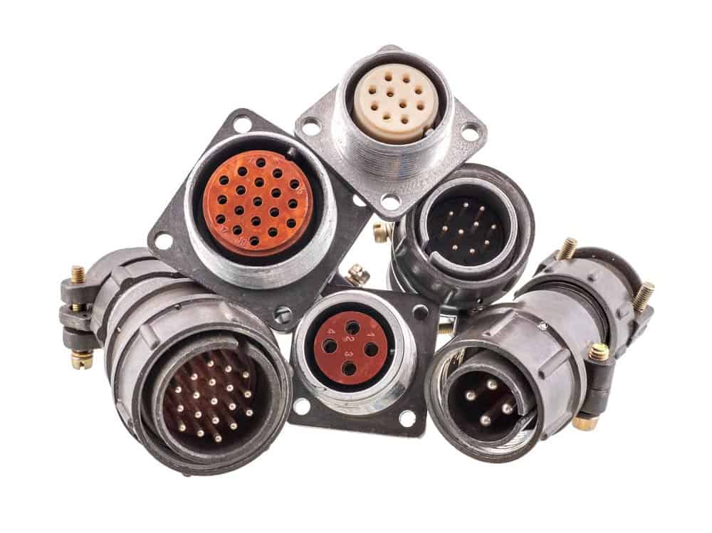
(Caption: RJ45 Connector)
Cat6 Cable Assembly:Cat6 Patch Cords and Cables Wiring Standard
Generally, Category-6 patch cords and cables get terminated in 8P8C modular connectors by either T568B or T568A pin assignments. Their performance is comparable as long as you terminate both ends of the cable identically. It’s important to ensure that for Cat6 wiring, you use Cat6-rated patch cables, connectors, and jacks to ensure effective performance and compliance with various performance specifications and standards.
TIA/EIA-568-B.1-2001 T568-A Wiring Scheme
Pin
Pair
Wire
Color
1
3
1
White/Green
2
3
2
Green
3
2
1
White/Orange
4
1
2
Blue
5
1
1
White/Blue
6
2
2
Orange
7
4
1
White/Brown
8
4
2
Brown
TIA/EIA-568-B.1-2001 T568-B Wiring Scheme
Pin
Pair
Wire
Color
1
3
1
White/Orange
2
3
2
Orange
3
2
1
White/Green
4
1
2
Blue
5
1
1
White/Blue
6
2
2
Green
7
4
1
White/Brown
8
4
2
Brown
Caption: Crimp Tool
Cat6 Cable Assembly: How to Crimp RJ45 Cat6?
If you’re looking to learn how to crimp an RJ45 connector, you’ve come to the right place. Follow the steps below to help guide you.
Step 1: Prepare the Cable and Remove the Insulation
Most professionals first mount the cable connectors before running the cable. Often, you can succeed because you don’t want to have to pull a connector through the conduit, wall, or behind furniture. First, remove the entire cable from the spool and lay it where you intend to use it. Use a sharp cutting tool or wire striper to strip off the outer insulation. If the cable has a non-metallic shield and core, cut them back. You’re left with four pairs of exposed ethernet wires. These pairs include blue, green, brown, orange, and their white counterparts.
Step 2: Cat6 Crimping Color Code
An important point in crimping an RJ45 connector is knowing the color code. There’s a diagram you can follow to help you properly position the wires into the RJ45 jack. Use the table below to help you make your way through this step.
Cat5e Wiring Diagram for T568B (Straight Through Cable)
RJ45 Pin Number
Wiring Color
1
White/Orange
2
Orange
3
White/Green
4
Blue
5
White/Blue
6
Green
7
White/Brown
8
Brown
Step 3 – Prepare The Wires for The RJ45 Connector
The wires observed in the last step aren’t as easy to maneuver as you’d think. It’s essential to take time to carefully sort out the wires to allow you to set them in the RJ45 connector properly. Otherwise, failure to do so will result in you having difficulty inserting the wires into the plug, increasing the chances of creating a poor crimp. If you’re unsure of the orientation, placing wires in the wrong position is easy. To succeed in this step, it’s best to use needle nose pliers that will help you save assembly time. Also, remember to use a sharp cutting tool to cut about half an inch of the wire to ensure the connector is biting the cable’s insulation. Failure to do so would increase stress on the signal conductors.
Step 4 – Prepare The RJ45 Connector & Crimping Tool
During this step, you’ll prepare the necessary tools for crimping. Insert the RJ45 connector into the crimp tool. Often there’s a slot to help keep the connector in place. Ensure you press the tool at the right time to avoid inserting the pins improperly, which will mean you’ll have to throw them away. This is important because RJ45 connectors aren’t reusable even when slightly misplaced.
Step 5 – Insert the Wires Into the Connector & Crimp
Some people opt to insert the wires while the connector is inside, and others prefer otherwise. Insert the wires accordingly and squeeze.
Step 6 – Verifying Your Work
The last step is validating your work. With RJ45 crimping, there’s often room for errors, hence the importance of inspecting your cable. You’ll need a cable checker complete with two modules. Place a module on either side to determine if you’ve established a reliable connection or need to re-crimp the cable. Never assume everything is okay, especially if you have multiple connections.
Caption: Cable Tester
Conclusion:
Wiring a Cat6 Ethernet cable isn’t as difficult as you might think, and it gives you endless customization options for your home network. At Cloom Tech, we provide all CAT6 and CAT6a cable assembly services. Feel free to contact us for the best services.
The high-tech world uses electrical and electronic devices in almost all areas of our life, and every application uses cable assemblies. People working with these cables must be careful while terminating cables, especially in harsh and dangerous environmental conditions. One such very reliable component for sealing cable ends is the cable gland. This blog post discusses cable gland assembly techniques.
What are cable glands?
You can use cable glands as mechanical cable entry devices in combination with cables and wiring for:
The cable glands mainly work as terminating and sealing tools; you can call them to cord grips, cable fitting, or cable connectors.
The function of cable glands
In addition to the protection of electrical equipment and enclosures, cable glands have multiple other functions, including:
Holding force
Cable glands also ensure mechanical cable pull-out resistance on the cable.
Earth Continuity
In armored cables, cable glands are present as a metallic structure. In such systems, you can test the cable glands to identify if there is sufficient peak short circuit fault current.
Environmental protection
Cable glands seal the cable sheath’s outer side, protecting from moisture and dust to the enclosure or the instrument.
Additional environmental sealing
At the entry point of the cable, cable glands ensure the correct rating of ingress protection with the help of different accessories.
Additional sealing
It also offers high ingress protection (if required) at the cable area near the enclosure.
Weatherproof
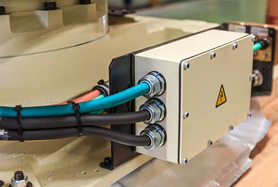
Cable glands come with an IP68 waterproof function which means you can use them to make watertight exit points in severe or adverse environmental enclosures or through bulkheads. The cable glands help compress a seal into a round cable so that there is no ingression of water or other particles which may damage electronic devices.
For example,
You must drill a hole to pass a cable through a watertight enclosure. As a result, it will no longer be watertight. To make it watertight again, you can use a cable gland to create a waterproof seal around the cable passing through the enclosure.
For cable from 3.5mm to 8 mm in diameter, an IP68 waterproof function works well.
Caption: electrical cable with connectors
Components of cable glands
You can determine the different parts of cable glands based on the type of cable glands. There are two types of cable glands:
Single compression cable gland
The single compression cable gland does not have a cone and cone ring. Instead, it only has a neoprene rubber seal to provide mechanical support to the gland when attached to the cable. The other parts of the single compression cable gland are:
Gland body
Gland body nut
Flat washer
Check nut
Rubber washer
Rubber seal
Neoprene
You can use these cable glands for lightly armored cables, and the cable has some scope of getting damaged through corrosion or moisture with these cable glands.
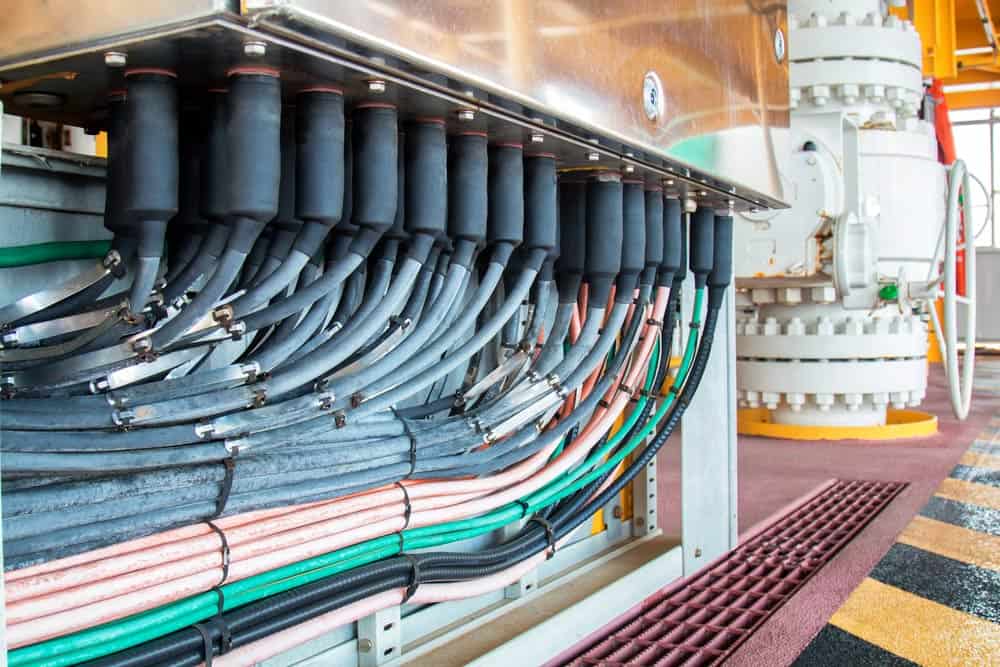
Double compression cable gland
This cable gland differs from the above as it has a double sealing feature. Its cone ring and cone offer mechanical resistance to the cable, and you can use them where large armored cables and wires are coming out and getting into the board.
These cable glands work as weatherproof or flameproof cable glands. The different components of the double compression cable glands are:
Check nut
Cone ring
Cone
Neoprene rubber seal
Gland body
Gland body nut
Caption: cable connectors
Specifications of cable glands
You need to consider several specifications before you pick one for you. Here are some.
Material
Cable glands are available in various materials.
Stainless steel cable glands have high-pressure ratings and provide corrosion and chemical resistance.
There are cable glands made of steel.
You can also opt for PVC or polyvinyl chloride cable glands featuring smooth surfaces, non-toxic features, and good flexibility. As PVC is passive, manufacturers use some food and chemical processing grades.
Apart from this, there are PTFE (Polytetrafluoroethylene) cable glands. These glands are highly resistant to chemicals and have a low friction constant.
There are nylon glands that are tough and exhibit a high-pressure rating.
Some others are made from brass, offering low magnetic permeability, good conductivity, corrosion resistance, cold flexibility, high-temperature ductility, and good bearing properties.
Some cable glands comprise aluminum which is a bluish-white metal. It is an easily malleable and ductile element and shows excellent thermal conductivity.
The metal also provides high reflectivity and resistance to oxidation.
Performance
The performance of the cable gland type is also essential which depends on the:
Complete ambient operating temperature
The pressure that a cable gland can bear without leakage
Size selection that cable glands can accommodate
Number of elements accommodated by assembly
Size of thread or mounting feature
Installation of cable gland
When installing cable glands, you must follow local regulations and codes of practice. Carry out cable gland installation only if you are an experienced person. You must have the skill and knowledge needed for gland installation and take training. Here is a guide to ensure cable glands’ safe and reliable installation.
Installation tools
While you carry out cable gland installation, you need to choose some cable gland tools that ensure the safe installation of cable glands without damaging any material or equipment.
PPE: Wear this to avoid personal injury while terminating or handling cables.
Digital Measuring Device: Check and record the cable size to verify it for each cable termination.
Spanners: You can use them to install the product correctly.
Armor forming tool: It helps prepare armor wires for the termination in the body of the cable gland.
Hacksaw: It helps to cut armor wires.
Outer seal tightening guide: You can correct the cable gland size.
Safety knife: It helps cut only the armor wires without damaging the bedding and insulation layer beneath them.
Electrical scissors: It helps remove excess cable braid. Ensure that you pick a sharp one so there is a clean cut without any snagging.
Cable Gland Assembly: Installation standards
The installation codes and standards for cable glands and accessories are:
1.IEC & EN 62444: for cable glands used in electrical installations
During installation, you can ensure safety in many ways, such as:
Ensure that you do not damage entry threads while installing cable glands.
Do not start installing cable glands in live circuits. Similarly, wait to open the glands until you de-energize the circuit.
Different components of cable glands are compatible with each other only if they are from the same manufacturer. Further, installing components from the same manufacturer ensures the safety of the installation.
Cable glands fall under certification protocols, and a manufacturer cannot sell the installed products’ spare parts.
The sealing rings of the cable gland come with cable glands right from the factory. Under no circumstances are sealing rings removed from the cable glands.
Do not expose sealing rings to dirt, chemicals, and other foreign bodies.
Cable Gland Assembly: Installation instruction:
Follow these instructions to install cable glands:
Detach the two components of the cable gland, i.e., the entry point and nut
Now, fix a shroud over an outer cable
The Remove the cable outer sheath and braid to properly manage the cable to fit into the equipment geometry.
Remove the outer sheath 18mm away to reveal the armor
Remove any wrapping or tapes to reveal the inner sheath if required
Now, secure the cable entry component into the equipment
Allow the cable to pass through the entry item and space the braid around the cone in an even fashion.
Prevent contact between the cone and the armor and screw the nut tightly to engage the armor.
With this, you complete the installation.
Cable Gland Assembly: Check the performance
After the installation, you must ensure the safety of the cable gland.
Sealing performance: Check the sealing ring’s suitability, functional performance, and reliability. The things that can affect the cable glands’ performance include material choice, sealing design, and valid and effective testing program. Different tests include pull-out resistance tests, thermal endurance, ingress protection, and cable anchorage.
Armor clamping: Loose armor clamping can also result in improper cable gland installation. Using the right armor cone and clamping ring ensures that you create the proper termination that secures the armor wires during the crimping process.
Earth Continuity: If you do not clamp the armor cables correctly, it will affect the potential equalization adversely. With the right armor clamping method, you can create a low-impedance termination that does not undergo self-loosening. Instead, it enables reliable earth passage.
Conclusion
The cable gland is a crucial component for cable assemblies and wiring harnesses. If you need help buying or installing cable glands, contact Cloom. We manufacture a wide range of cable assemblies and deal with all the related components, and our team has extensive knowledge about the cables used in different applications.
When designing a project, don’t think of the wire or cable harness as a bunch of wires. Be careful not to focus all your attention on the design’s function, form, and features, and leave the wiring for the last steps. Doing so could later result in some complications, especially if your project primarily involves consumer appliances and the electronics industry. Now let’s discuss your choices when designing a consumer cable assembly.
What is Consumer Electronics?
Home or consumer electronics refers to any analog or digital devices used daily in private homes, including communication, recreation, and entertainment equipment. It is often referred to as black goods because they mainly come in darker colors. In comparison, devices used for housekeeping and cleaning, such as fridges and washing machines, are referred to as white goods because they generally come in light colors. However, today the line between white and black is somewhat blurry. In the British English Community, sellers and producers refer to some products as brown goods. Most large consumer electronics stores that sold white and black goods in the past had no distinctions.
In the early 20th century, radio broadcasting introduced the broadcast receiver, the first major consumer product. Later other products were developed, such as TVs, calculators, telephones, video recorders, mobile phones, gaming consoles, MP3 players, and personal computers. In the 2010s, more consumer electronics were developed, such as car stereos, GPS, electronic music instruments, video game consoles, video players, digital cameras, and karaoke machines. Stores began selling smartphones, cellphones, small light fixtures, camcorders, and digital cameras. Some newer consumer products include smart home devices and VR head-mounted devices. Over time consumer products began merging with digital technologies and began increasingly called the consumerization of information technology. Today consumer electronic stores also sell baby and office furniture. Furthermore, the stores have expanded combinations of both physical and online stores.
Household appliances
Consumer Cable Assembly Understanding
Manufacturers designed wiring harnesses for use in various electronic products and home appliances. These electronic and home items are key in exchanging signals or data and supplying power. When used in mobile phones, PCs, TVs, gaming instruments, or digital cameras, professionals refer to a wire harness as a consumer-use wiring harness.
Serial DMI
How to Design Consumer Appliance Wire Harness
Here are some key points to consider when designing your wire harness:
Every component of the harness could affect the finished product.
To serve specific environmental conditions, you must design coverings, wires, and connectors.
Always consider operating temperature, voltage, and amperage when making decisions.
Wire Harness Assembly
The length of the wire does not necessarily determine its price because assembly time has a heavier impact on the cost should you make a mistake.
A common mistake people make is during the routing and bunching of wires. Ensure you lay out the wires clearly to avoid making mistakes.
Because of the large potential of terminations, ensure the design is simple to avoid placing terminals in the wrong place.
Wire Harness installation
Here, the wire and heat-resistant connectors’ costs are lower than the cable installation. Therefore, ensure to keep that in mind while making decisions.
Although spinal cord designs have more wires than spider web designs, they are easier to install and service.
The Connectors
Your connector choice depends entirely on the speed and type of signal you plan to transmit.
If you plan on sending power through, opt for a crimp-type connector.
Also, choose a welded or soldered connection if you intend for it to transmit a high-speed signal.
Keep in mind the final assembly has a specific connector. Therefore, you have limited terminal choices.
The Conductor or Circuits
The number and type of conductors or circuits depend on your application.
Copper is often the preferred conductor material because it is compatible with various coatings slowing the corrosion rate.
You could use copper alloys or copper-clad steel if you need more breaking strength.
The Coverings
The wire covering offers an extra layer of protection and insulation against fluids, chemicals, abrasion, heat, vibration, moving parts, rattles, moisture, and rattles. Also, flexible wire coverings protect against EMI.
Some wire coverings include:
Cable protection sleeve: Wrap or expandable sleeving is easy to install and highly flexible, enabling quicker wire bundling. Often, braided sleeves use PET because of their lightweight design, durability, and flexibility, even under low temperatures.
Tape: You can find pressure-sensitive single-coated tapes in many backing materials and adhesives. You can use PVC as the backing material. However, some tapes use felt, foil, cloth, or foam. With tapes, stiffness is often an issue because it minimizes flexibility.
Heat shrinking tubing: This tubing wraps around wires, smoothing the surface and providing electrical and thermal insulation. Also, adhesive-backed tubing serves as a seal against chemicals and moisture.
Split loom tubing: This has a slit on the sides of the covering for easier wire insertion. After installation, you must seal the slit to eliminate the need to heat shrink or spot tape. There are several materials, with the common choices being split wire mesh loom and steel braided wire loom.
Spiral wrap tubing: It allows wires to exit and enter the covering at multiple points. Professionals often use polyethylene and polyamide, available in various colors for easier identification.
When designing a wire harness, it’s important to consider every aspect of the design, particularly the environment you’ll expose it to. Consider the following:
Can every component withstand the required operating temperature and voltage?
Are the harness mounting and connector designed to relieve pressure from extreme vibrations?
Does your harness need to contend with moisture, detergents, or grease?
Is flammability a concern?
Consumer Cable Assembly: The Safety Standard
Safety is vital when designing a wire harness. Therefore, ensure your design complies with the necessary standards, keeping in mind that every country likely has different federal standards enforcing the testing and certification of electrical devices. Most countries use the following guidelines as the backbone of their standards.
International Electrotechnical Commission
European Committee for Electrical Standardization
International Commission for Rules for the Approval of Electrical Equipment
The IPC/WHMA-A-620 Standard Revision C is the only industry standard for Requirements and Acceptance of Cable and Wire Harness Assemblies. And the WHMA and IPC are continually working on developing helpful updates.
Consumer Cable Assembly: The Environmental Standard
You should be familiar with the three standards limiting the use of hazardous substances:
The WEEE Directive governs the disposal and recycling of electrical products once they’re no longer usable.
In addition, concerning the safety and federal environmental standards, assemblies may have to meet standards based on specific performance criteria. Also, depending on your intended application, you may have to meet additional standards and certain criteria, such as QSFP, HDMI, or independent testing services such as ETL.
Different types of Consumer Appliance Wire Harness
Consumer Electronics Connector Products
Some examples of consumer electronic connector products include:
Consumer Cable Assembly: 868 Series spring-loaded and target connectors of Military Max Mfg. Corp.
This product features a sturdy solder cup termination accommodating the cable and wire attachment as it also handles the insulated flanges and securing options to accommodate further application stability.
The connectors are soldered and come in a pitch of about 4mm, with the pins uniformly aligned to efficiently facilitate soldering various wires of up to 16 AWG. Professionals use these connectors for mounting inside component housing for cable terminations, robust quick connections, and docking stations.
Also, the connectors have robust pins with diameter plungers of about 1.27mm, capable of resisting binding and bending while applying side loads. Further, the connectors feature a stainless steel gold-plated spring delivering reliable operation during countless cycles. That’s because the gold-plated spring is less likely to undergo stress relaxation while operating overtime under extremely high temperatures than other options available.
Every spring pin has a 9A rating with a 10°C increase while providing a cable stroke of about 2.29mm and contact resistance (lower than 20mΩ). With mating intended connectors, you can choose between a concave or flat face for the pin’s mating side.
The Mill-Max Mfg. Corp’s 868 Series is also equipped with nylon 46 high-temperature molded insulators compatible with joined mounting tabs, enabling secure attachment of the product to PCBs or the finished product housing. In addition, brass components provide corrosion resistance, durability, and high conductivity.
Consumer Cable Assembly: Solid signal double lock connectors of TE Connectivity:
With cap and plug housing, you can get wire-to-board and wire-to-wire single-row configurations. Also featuring 2-10 wire-to-wire or 2-13 wire-to-board crimp contacts with a pitch of about 2.5mm.
Professionals usually use these connectors in signal circuits for household appliances and consumer products. The connector features two internal lock plates, ensuring correct mating and a neat appearance. It also has polarizing ribs on the plug housing, polarization pegs, soldered tail kinks to enhance board retention while soldering, and audible mating confirmation.
The TE connectors are compatible with 20-26 AWG wires with an insulation diameter of about 1.8mm. They’re also available in various colors, all UL-recognized, TUV-approved, and CSA-certified. You can get mounted board headers in either standard or special versions compatible with conformal coatings and resin. However, you could opt for the radial tape-mounted model for radial mounting machine applications.
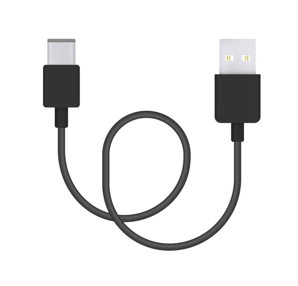
Consumer Cable Assembly: USB type-C waterproof connectors of Amphenol ICC:
Its primary capability is delivering up to 10Gbps, facilitating super fast communication while supporting USB 3.1 Gen 2 and 1 protocols, and backward compatibility with USB 2.0.
Caption: Type-C cable connector
This connector is almost equal to the micro USB cable connectors but has a lower profile casing with cable orientation and reversible plug for a better user experience. It’s ideally used in datacom, consumer, telecom, medical, automotive, and industrial applications. However, it’s also applicable in mobile phones, flash drives, tablets, hard drives, virtual reality setups, high-temperature drives, point sale systems, industrial computers, infotainment systems, and car charging outlets.
Caption: Micro USB cable
The Amphenol ICC’s waterproof USB type-C connector also features terminals of quality copper alloys. Also, the front-end insert molds for IPX2 to IXP8 in a right angle standoff, 24-pin assignment to enable compatibility with various video and audio signal product protocols, O-rings, straddle mounted configurations with a rating of about 10,000 cycles, and waterproof glue.
Alloy 174 military-hardened copper-beryllium alloy striped material of Materion:
Professionals usually use these connectors in high-density, miniaturized, telecom, automotive, medical, aerospace, and datacom. You can also use them for terminals, connectors, and contact springs for relays and switches. Their design enables them to recover the cost and performance differential among the lower-performing copper alloys, for example, beryllium copper and brass.
Further, manufacturers designed Alloy 174 to facilitate conveying high current facing low-temperature increase while exhibiting stress relaxation resistance at extremely high temperatures. In addition, a higher electrical conductivity than most copper alloys, increased thermal conductivity, formability-to-strength ratio, predictable, regular forces, and impressive reliability.
The Alloy 174 can withstand stress with strengths of about 125 ksi, which is far better than other strip alloys such as silicon bronze, brass, phosphorous bronze, and alloys of copper-nickel and aluminum. Also, it offers longer thermal stability and higher spring force maintenance while easily conforming into any shape, enabling withdrawal forces, low insertion, and extremely unvaried cycle lives.
Upon exposing the Alloy 174 to stress, for example, the strength of up to 45 ksi during the intense reverse bending process, its cycle life will still maintain countless operations. The material used in Alloy 174 offers stain retardant treatment providing temporary protection from surface link growth, such as oxides in industrial areas with higher humidity rates.
You can get the material in solder coating, rare metal inlays, and tin plating. Rest assured that it’s compliant with UNS C17410, ASTM B 768, and AST B 888 standards, enabling simpler integration alongside various specifications and existing projects.
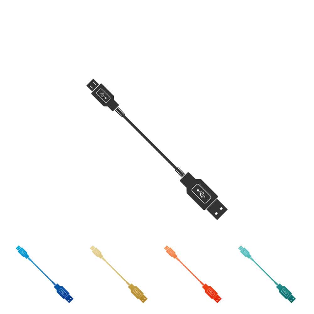
JF08 Series internal high-speed harness assemblies of JAE:
They comprise flat flexible cables compatible with fast differential signals primarily applied when interfacing with camera modules, OLED/LCDs, and a variety of daughter boards. These boards include PCI-E, USB cables, LVDs, single row 51 or 41-point plug connectors, adaptive locking latches for proper mating with the FI-R Series outlet connectors, and large guideposts for easy alignment.
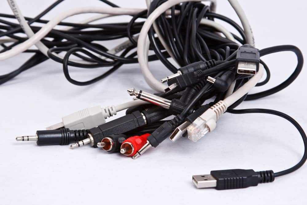
Caption: USB cable types
Professionals use these connectors to design consumer electronics, such as servers, PCs, monitors, TVs, speakers, printers, gaming systems, and several communication devices. Assemblies come in standardized lengths of 40cm, 30cm, and 20cm, capable of folding to meet various cable design routing specifications in space-constrained uses. Each contact has a 0.3A rating, with the highest contact resistance being about 30mΩ, minimum insulation of 100mΩ, and dielectric withstanding voltage of 250 VAC/rms. In addition, it can operate at temperatures ranging between -30°C and +80°C. These connectors are also RoHS-compliant and provide accurate impedance matching.
Schleuniger’s RotaryStrip 2400
It features high precision, flexible, and fully programmable stripping machine with the ability to process 10-36 AWG solid or single and multi-conductor cables or stranded wire made of various insulation materials such as Teflon, Kaptin, and fiberglass that don’t require mechanical adjustments.
You can also use the Schleuniger connector to twist and strip a range of wire sizes from 13-26 AWG while still performing any forms of stripping from the multi-step, full strip, and partial strip. Furthermore, the machine has a state-of-the-art touchscreen interface, allowing users to quickly input and keep records of a couple of programmable processing variables, such as feed rate, pull of speed, and stripping diameter and length. That allows for broad use stability while providing users with a full picture of the working space.
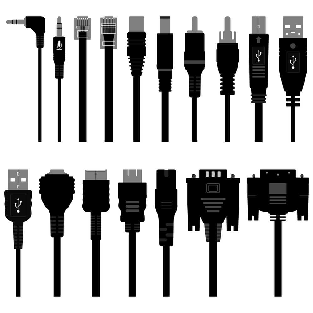
TE Connectivity’s USB type-C cables and waterproof connectors of Heilind:
They provide power, video, and audio connectivity, increased EMI protection, and data. In addition, IPX4 splashproof or IPX8 waterproof protection for industrial, consumer, automotive, medical, telecom, and datacom applications.
Professionals also use the Heilind connectors in tablets, smartphones, wearables, power packs, laptops, chargers, data centers, lighting systems, infotainment systems, and factory automation equipment. At 5A or 20V, connectors can transmit power of up to 100W and 10Gbps while maintaining a strong housing equipped with a changeable mating interface and increased board retention capabilities. Also, a solid dual-row surface mounts technology footprint while supporting various protocols such as USB cables 2.0 and USB 3.1 Gen 2 or 1. Moreover, the machine utilizes converter cables or adapters such as VGA, DisplayPort, HDMI, and various other connections.
Caption: Cable connection types
Consumer Cable Assembly: ACES 50696-XXXXX Series Connectors:
ACES Connectors’ surface-mount technology (SMT), flexible printed circuit (FPC), zero-insertion-force (ZIF) connectors comprise 19 standard circuit options with 4–30 high-performance phosphor bronze contacts, back flip actuator, 0.5mm pitch, and a low height profile of 1.06mm.
You can use these connectors with reflow and hand soldering processes and with high-temperature thermoplastic or only thermoplastic and actuator materials. The connectors can also support the fast transfer of USB 3.0 data and feature a fitting copper alloy nail and accepting cable up to 0.3mm thick.
The series has a maximum of 60mΩ contact resistance, 0.5 per pin rating, 20-cycle durability, and 200 VAC/rms dielectric resistance voltage. Also, it can operate under temperatures ranging between -400C to +850C and the lowest insulation resistance of 500MΩ.
Cat 6A Z-MAX 6A shielded outlets of Siemon Interconnect Solutions:
They utilize remarkable Cat6A performance and exceptional termination time, surpassing the necessary industry standards. They’re crucial to the end-to-end Z-MAX 6A shielding cable systems.
These outlets consist of various components, each performing a specific duty. Strong die-cast housing performs the following duties:
Strong die-cast providing optimized shielding against alien crosstalk and EMI.
Diagonally positioned IDC contact layout increases separation of pair-to-pair, decreasing alien crosstalk even in the most concentrated Cat 6A patch environment.
Zero cross-level termination elements enable acceleration of lacing while eliminating crossed pairs and splits.
You can opt for a door that has been spring-loaded and is capable of reducing exposure to contaminants and dust, enabling easy single-finger use.
A pass-through technology that allows rear or front faceplate mounting.
The hybrid design allows mounting outlets of the same type in angled or flat orientations.
Integrated coupled metal clip relieves cable strain and quick shield connections.
Also, Simeon’s products have patented jack-crowned contact geometry that enhances mechanical and electrical performance.
Thanks to the Z-Too, you can perform quick terminations, enabling fast and coupling with low force. Additionally, you can get shielded outlets in various colors, with several accessories and colored icons to enable easier port identification, all of which are by several industry standards and ETL tested.
Conclusion:
With the consumer electronics industry constantly undergoing innovations, it’s important to stay updated. Fortunately, Cloom Tech offers customized electronic wiring harness solutions to meet ever-changing requirements. We have a variety of premium wire harnesses and cable assemblies built from high-quality materials, available in a wide range of dimensions and colors to meet your specific federal standards. Contact us for the best custom wire harness and complex cable assembly services.
When designing a custom wire harness and custom JST cable assembly, you’ll often need to use JST connectors. However, there’s much to know about JST connectors to effectively use them for your project.
What are JST connectors?
The JST connector got its name from Japan Solderless Terminals, a Japanese company. The company has several connector series. The company designed the electric connector as a terminal that would not need soldering. Its sleek design and remarkable features have made it a common choice for various electronic projects, batteries, 3D printers, motors, PCBs, and servo motors.
Professionals use JST connectors to convey signals or electric currents in electronic projects. However, manufacturers recommend you avoid using them in mechanical applications that subject the connector to tension and other types of force. That’s because the connector will fail to resist the force.
JST Connector Standards
It’s essential to mention some aspects of the JST connector standards that often confuse users. Firstly, there are ten families of various JST connectors, each with subcategories and models. Therefore, the term JST applies to the general solderless connection that all the connectors have in common, not a specifically categorized connector.
To differentiate between the connectors, professionals normally use the JST-SS-D nomenclature to verify the names.
JST: refers to the connector
SS refers to the family or series and sometimes is preceded by a different letter. An example is X, thus XSS. The preceding letter describes the connector’s shape and specifications (size, voltage, and current).
D: refers to the dimensions within the series.
To ensure proper operation of the custom connector and prolong the connector’s lifespan, there are a couple of manufacturer suggestions to keep in mind:
Ensure the JST cable is slightly longer than required to avoid cable stress.
While disconnecting the JST cable connector, never pull on the wires, as you could loosen them up.
Ensure you limit room for movement to about 15 degrees in every custom cable.
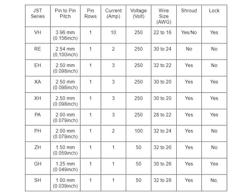
JST Connector Series
Below is a table to help you navigate types of wire-to-board connectors.
However, for wire-to-wire connectors, you’ll require different guidance. Below is the table to help you.
JST connectors can be found in a wide variety of products across many industries. Select a category below to explore how they are used.
JST SH
This wire connector has a spacing of about 1.5mm between the connecting pins. It features a 4-pin variant, a common JST connector often used in laptops and most flight controllers.
JST GH
Though similar to the SH connectors, the JST GH features a 1.25mm pin spacing. And if you take a closer look, you’ll notice the pins are bigger and spread wider apart. Also, the plastic housing is taller and thicker. Manufacturers designed the JST GH connectors for use in small video cameras. Despite the connectors having a different number of pins, the spacing is always a standard 1.25mm.
JST ZH
The JST ZH connector features a 1.5 mm pin spacing. These connectors are pretty rare compared to other connector types. Professionals use JST ZH connectors mainly in satellite receivers and, in some cases, 3D printers.
JST PH and PA
The JST PH and PA connectors feature a 2mm pin spacing. However, they differ in current capacity. The PH connector’s current capacity is 2 amps, while the PA connector has a current capacity of 3 amps. Professionals use these connectors in fabricated hobbyist PCBs and low-quality electronics primarily because of their low price and compact nature.
JST XH / XA /EH
The JST XH/ XA/ EH connectors have a pin spacing of about 2.5mm. The connector on the circuit determines the type of connector you’ll need, as each has a different number of input wires. In terms of current capacity, each connector offers the same capacity of 3 amps. Professionals often use these connectors for low-consumer products.
Although the connectors have similar characteristics, they come in different shapes. Therefore, you can use an EH instead of an XH. People consider the XH connectors a larger version of the previously mentioned PH connectors. The resemblance is in the head design and the tall plastic housing.
People rarely use the JST XA connectors since most projects require the XH connectors. Professionals mostly use JST XA connectors in Japanese-made LED TVs and other products.
JST Connector Crimping
Manually crimping JST connectors is challenging. Therefore, people often buy crimped wires that slip easily into the connector housing, creating any sequence. However, some people prefer to make their crimps. Read on to learn more about creating a crimp.
Custom JST Cable Assembly: A Good Crimp
Before diving straight into creating a crimp, let’s first discuss what a good crimp entails. When purchasing crimp connectors, you’ll notice some metal strips attached. These strips should go through a machine that automatically creates a crimp. However, we are looking to accomplish this manually.
Every crimp connector has two sets of wings you’ll need to bend as the process continues. The first set holds the insulation, while the second holds the wire. After the wires are crimped, they snap directly into the plastic housing, ganging them together. Upon pushing the wire inside the housing, you’ll hear a click. Just be careful not to cause too much damage to the crimp connector.
Custom JST Cable Assembly: Crimping Tools
You’ll need to get a variety of tools to do the job. Ensure you get the best tools. Otherwise, you’ll need to crimp twice (first for the insulation and again for the wire). Also, ensure the tools are not hard to use to minimize room for errors. The key difference between the PA-20 and PA-09 is the scope of crimp sizes.
If you find the PA-09 ineffective, you could opt for the JST crimpers. The JST can crimp both wings at the same time while automatically positioning the crimp connector to its rightful position. However, it only works for one type of connector, the JST-PH.
Custom JST Cable Assembly: Crimping Procedure
With crimping, you have to be careful to avoid mistakes. Although there’s no definite procedure for creating the crimp, below is a general flow to guide you.
First, strip the ends of the wire and twist them a little bit. You’ll need a stripping tool to create a perfect strip of about 2 to 3 mm.
The next step is to break the crimp connector away from the strand. Then, hold it in one of your hands and push the wire wings inside the appropriately sized tool. Make sure the crimp is pointing to the crimper as they bend backward. Also, ensure the outer insulation wings aren’t inside the crimper because you only want to crimp the inside wings of the first crimp. After this, don’t jump straight to crimping. Instead, push down slightly to ensure the crimp connection is held in the same position while using your other arm to lift the wire.
Next, push the wire inside the crimp connection, ensuring the plastic insulation ends at the crimper’s edge without sticking out of the connection. Sometimes the connection might be too large to fit inside the connection or sides of the crimp to prevent it from slipping in.
Now, the next step is to crimp. Ensure the wire strands stay beneath the folded wings while the outer wings remain open.
Follow up by using the end of the crimp to slightly bend the outer wings so they can fit inside the crimping tool. Ensure that they’re parallel.
Finally, put in the crimp connection from the opposite end and crimp.
Often, while crimping JST connectors, people encounter the following challenges:
Over-crimping or bending the connection.
Stripping too much or too little wire.
Not pushing the wire far enough, and as a result, failing to crimp the insulation.
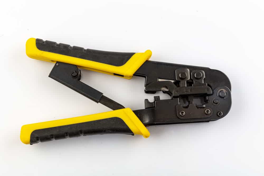
Caption: Crimp Tool
Conclusion:
There you have it all you need to know about JST connectors. Feel free to reach out to Cloom Tech for all your custom cable assemblies. Our team of professionals has extensive experience in designing cable assemblies to the exact customer design, guaranteeing you get what you want.
Automation in the house and factory relies on the gadgets’ communication abilities. People expect that industrial equipment should communicate with one another as technologies evolve.
D-sub connectors were the standard for making connections before twisted-pair connections became commonplace in factories. Furthermore, D-sub connectors have been around since the ’50s and still are a popular choice for today’s equipment. Let’s check out the D-sub cable assembly explicitly built for this project.
What are D-sub cables?
D is for “D” shape connectors. As an acronym for “sub-miniature,” “sub” means something smaller than a standard miniature. It’s a multi-wire cable with “D”-shaped plugs at each end.
There are different “standard density” pin counts for sub-connectors, such as 9, 15, 25, 37, and 50. Also, these cables can have high-current connection pins and coax connector pins, which adds an extra layer of complexity. There are component engineers whose sole job is to keep track of all the permutations of configurations.
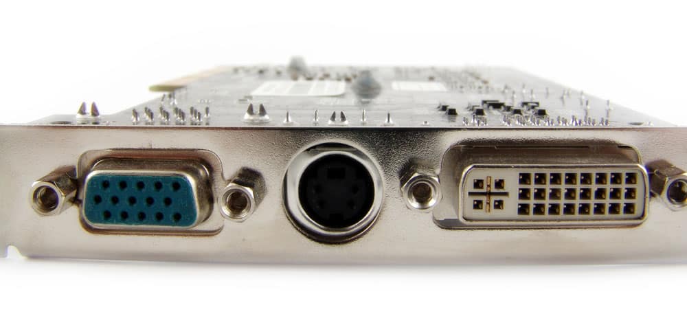
VGA cables are the most common type of D-Sub cable that you can find in homes with a standard density of 15-pin. Moreover, you may find it in machinery for operating a “lift chair” with an average thickness of 9-pin.
These cables usually use multi-conductor wire with a grounding shield. The protection prevents interference from getting into your electronics by blocking RF sounds and signals.
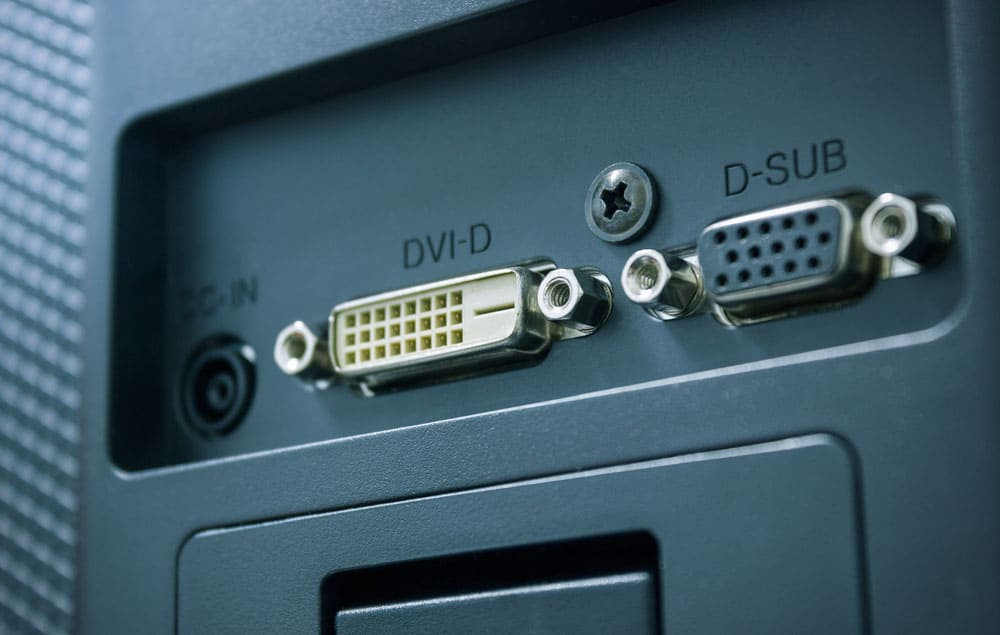
Among the many possible industrial applications is the transmission of control signals during the production process, Electronic testing, and the interconnection of various components of CNC routers, Press Brakes, etc. Some could even be in your automobile.
Caption: Computer Monitor Port
Typical applications of D-sub cable assemblies
Here are some common examples & applications for D-Sub Cables
Communications ports
You can find D-sub connectors in RS-232 serial transmission, but this is not because they meet any standards. Although DB25 was a popular choice for these devices, signal degradation forced people to switch to DE-9 Connectors.
The IBM PC, for instance, employs both the male and female connectors found on the modem. You can also find DE-9 in the serial interface on Apple Macintosh computers.
Network ports
When manufacturers first introduced the DE-9 adapters, they used a combination of Token Ring and other network technologies.
In the 1980s, electricians utilized a DA15 connector for connectivity on attachment unit interfaces. The sliding latch was far more dependable in these systems than the jackscrew.
Computer video output
The IBM PC’s visual output was a female 9-pin connector. In theory, you could connect different kinds of outputs to the same connector, but this could hurt the interface.
Therefore, the VGA cables with their DE15 high-density connections were visible much later. Manufacturers also included the “D-Sub 15-pin” connector sockets for RGB video output on many Apple Macintosh models.
Game controller ports
The industry used the DE9 connector on the first Atari gamepad. As they made it out of plastic, it lacked the jackscrews required to secure it in the socket. The connector used by the game ports eventually became standard across various gaming consoles.
Others
There were external floppy drives in the original Macintosh and the Apple II that came after it. D-sub connectors make it possible to connect hard drives and printers, and both Apple and Atari’s 16-bit computer lines have them.
In addition, several manufacturers have integrated D-sub connections into their video and audio transmitters.
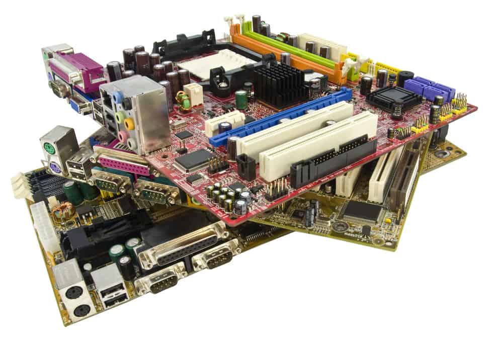
Caption: Ports on Video card
Wire-contact attachment types
D-sub connectors help attach wires and come in six different varieties.
Insulation Displacement contacts:Ribbon cables are inserted into pointed tines on the contacts’ reverse side with insulation displacement contacts. That allows you to penetrate the shielding of all the wires simultaneously. Whether you do it manually or using a machine, it doesn’t take long.
Solder Bucket: The stripped wire is placed into the cavity of the soldering tool before being hand-soldered.
Wire-Wrapped Connections: Solid wire-wrapped connections are wrapped around the square post using a wire-wrapping tool. That is a valuable type to have on hand while creating prototypes.
Crimp Contacts: Wires are inserted into the crimp contact’s cavity in the back, which is then compressed using a crimping tool. That allows the cavity to grab the wire in multiple locations effectively. The crimped contact is then inserted into the connector and then removed with the use of dedicated equipment and methods.
PCB pins: PCB pins are soldered into the board without wires. Initially, THP board-style connectors were standard, but these proved problematic when they faced mechanical force. That explains why PCB connectors became standard in electronics.
Caption: D-Sub miniature port on the motherboard
Advantages & Benefits of D-Sub Connectors
Some users may not understand why D-Sub connections are still in the market when more advanced options exist. Compared to USB, USB-C, and MDP connectors, D-Sub connectors have a variety of benefits.
Secure Connection: D-Sub connections are popular because of their lock-down feature, which ensures that the link remains safe even after being subjected to vibration and jostling.
Design Flexibility: Standard D-Sub wire assemblies can have anything from 9 pins to 50 pins, and high-density variants can increase that to 78 pins, albeit most users are only familiar with the nine-pin and 15-pin connectors. Additionally, they provide simpler connection rewiring, reconfiguration, and fine-tuning.
Cost Efficient: D-Sub cables are more affordable than other types of connections because of the low cost of the components and the ease with which they may be assembled.
Large Variety: D-Sub cable assemblies can be either through-hole or surface-mounted on a printed circuit board, can be stacked, and feature EMI/RFI filtering for extremely noisy settings. Solder joints, crimping, insulation displacing, wire-wrap, and mass terminating are all viable alternatives for securing the ends of D-Sub cables. With combination connectors, you may get an even reduction in the number of signaling contacts required for coaxial, high current, or high voltage links.
Multiple Uses: D-Sub connectors are the greatest option for many media applications in televisions, video games, and recording equipment because of their low cost and reliability.
Longer lasting: D-Sub cables are built to last, making them ideal for mobile use where frequent reconnection and bumping are potential wear and tear issues.
Custom D-sub cable assemblies at Wiringo
Custom D-Sub connectors can help fit the needs of any design, even in extreme conditions. These cable connections can function as input/output connections. They can pair with a printed circuit board (PCB) or wire connectors. Crimps and solder buckets are an option. Using hoods and lock systems, you can avoid accidental un-mating and lifting.
Here are a few options we offer you
Standard and industrial D-Sub connections with a single or double end.
Termination of various Custom Serial Cables, such as D-SUB, DB9, DB15, DB37, DB25, HD50, etc.
Unshielded and Shielded Wires
Heat-shrink and bespoke labels
Shielding, jacketing, inner/outer molding, contact electroplating, and bolt types.
Most of these gadgets’ connection points are D-sub connectors. They make connecting them to a network or transmitting audio/video signals easy. You can customize these ports and make them robust, flexible, and secure. Here at Cloom, we offer wiring harness solutions and custom cable assemblies to make your connection safe and reliable.
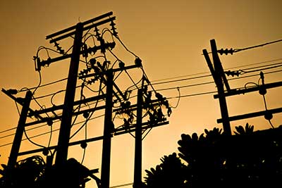
Have you ever seen overhead cables outside your house or in the markets? Have you ever noticed underground cables? All these cables are power cables that help in the transmission and distribution of electric power. You will find a wide variety of power cables in the market; however, you have to choose a specific type for a particular purpose to ensure smooth electrical performance. Yes, a custom power cable assembly.
What are power cables?
Power cables comprise one or more conductors bound together with an outer sheath. This assembly of multi-conductor cables helps in the transmission and distribution of electrical power. Different applications for power cables include their use within buildings or construction sites as permanent wiring, burial inside the ground, overhead cables, or even exposed cables.
Caption: electricity plant
Construction of power cables
They comprise three parts; conductors, insulation, and the outer cable cover or protective jacket. These components may differ in different power cables due to three main factors.
Working voltage as it decides the insulation thickness.
The current rating of the cable determines the cross-section area of the conductor. Also, power cables generally have copper or aluminum conductors in stranded form; however, some may even have solid conductors. Some cables may also have uninsulated conductors used for neutral or ground connection, known as tinned bare or bare conductors. The power cables may be round or flat; some cables have non-conducting filler strands to maintain their shapes.
Environmental conditions like water, temperature, sunlight, chemical exposure, and physical impact determine the outer jacket’s form and composition. For the nuclear industry, the jacket must have ionizing radiation resistance. For buried cables, the jacket must protect dig-ins or backfills; thus, polypropylene jackets are standard for these cables.
Apart from the main three, power cables may differ according to the situation, such as:
When directly buried or used in exposed installations, power cable requirements include metal armor of steel or aluminum. This armor is either in the form of a corrugated tube wrapped around the cable. The armor connects to the earth’s ground to avoid electric current conduction.
Power cables sometimes have armor wires on the jacket’s surface to support the cable’s weight in different applications. Electricians use a supporting plate at the tower or building floor in vertical cable installations.
If used in raceways, the cables may have electrical conduits or cable trays having one or more conductors.
For buildings, there are NM-B cable or non-metallic sheathed building cables having two and more conductors inside a thermoplastic insulated sheath.
Power cables for overhead applications comprise high-strength alloy, alum weld messenger, or ACSR. These are aerial cables or pre-assembled aerial cables.
When power cables face mechanical stress, the cables come with flexible steel tape or a jacket of wire further covered with a water-resistant jacket. Some utilities use lead sheaths as an overall covering of the cable.
Lastly, some power cables are hybrid, with conductors for transmitting signals and optical fibers for transmitting data.
The flexibility of power cables
The power cables have some flexibility so that shipping and installation become easier. However, the flexibility of power cables differs, putting them in different stranding classes.
There are three stranding classes for power cables: A, B, and C. These cables differ based on their minimum bending radius. Based on these classes, a cable is trained to be installed in the final position so it does not get disturbed. All these classes are highly durable and cost-effective also. Power utilities mainly use class B stranded power cables for primary and secondary voltage installations. However, when water blocking is a priority, one can use solid conductor cables with medium voltage.
For applications that require constant movement of power cables, like in portable devices, you may need flexible power cables or cords. These cords or flex have stranded fine conductors, and these conductors have jackets with filler materials to maintain their overall flexibility and durability. There are flexible power cables for machine tools, robotics, or other automated machinery.
Caption: power cables
Types of power cables
The construction of power cables differs based on their application, size, construction, type of material, current carrying capacity, and so on. However, based on voltage, power cables are of two types.
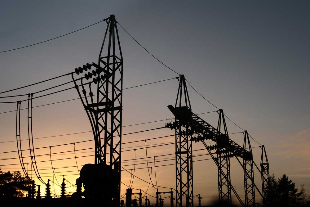
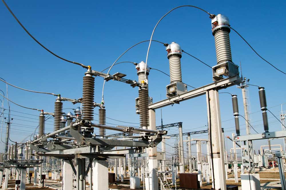
High voltage cables
As evident from the name, the high-power cable assemblies help in high-voltage transmissions, specifically in transmissions and power plants. The voltage of these cables varies between 33Kv to 220kV. You will find these cables mostly in power grids. These cables have very high-current carrying efficiency. However, with such a high current and high voltage, the insulation requirements of these power cables are also high. Thus, you will find a very high layer of insulation in these cables, ensuring reliable transmission.
Further, technicians use many automated technologies like SCADA or DCA to ensure that transmission occurs safely without risk to humans and surroundings.
Low-voltage cable
The voltage capacity of these cables falls between 70v to 600v; thus, you can safely use them for domestic, small-scale industries and various applications. A large number of factories and various automated technologies use these cables.
Be it high- or low-voltage cables; it is never safe to touch either of them; otherwise, it may result in death. High voltage cables carry high voltage current, which is stepped down at substations and reliably reaches homes and offices through low voltage cables.
Caption: high voltage substation
Power cord standard
You must have the power cord in your mind when it comes to custom power cable assemblies. Power cords have different quality standards worldwide, and different countries use different power cords, plug types, and connectors.
IEC 60320
is an international standard for power cord appliances up to 250 volts. Though different countries use different power cord standards and types, this is a common standard that most countries use. Here, the C refers to the connector code standards defined by IEC 60320. You must pick different connectors for current, voltage, and temperature combinations.
In data centers, the standard connectors used are C13, C15 and C19.
The IEC 60320 power cords define an even number for the plug connector and an odd number for the female receptacle. Here, the male plug number is one higher than the corresponding receptacle connector number; for example, the standard power cord type combinations are C14 to C 13, C20 to C19, etc.
The IEC 60320 standard mainly focuses on the connector types. For the plugs, the different countries use different standards.
Custom Power Cable Assembly: North American: NEMA 5-15P (Type B)
Most North American countries use NEMA standards. Among several NEMA plug standards, NEMA 5-15P plug is the most common. There is a three-wire circuit where one wire is for hot, the second for neutral, and the third for ground. These plugs have a rating of 250V and 15 amperes. The most common power cord is NEMA 5 15P (plug) to NEMA 5 15R (receptacle). Other common combinations include NEMA 5-15P to C15 and NEMA 5-15P to C13.
Custom Power Cable Assembly: Europe: CEE 7/7 (Type F and Type E)
CEE 7/7 is the widely used industry standard for plugs in most European countries and countries that follow CENELEC standards. European countries like Cyprus, Malta, Denmark, and Switzerland do not use CEE standards. The typical power cords adopting CEE standards are CEE7/7 to C19, C15, and C13.
Custom Power Cable Assembly: Other standards:
The table below lists some countries with different plug standards.
When choosing power cables, commitment to quality is required to avert any potential risks and sudden electrical faults. Before any installations, it is always good to seek professionals’ advice. Further, if you need custom cable assemblies, Cloom can help you get one suitable for your application requirements.
You will often need cables that can bend repeatedly and plug or unplug for industrial and automotive applications. To achieve your goal of reducing mechanical stress and providing strain relief, you will require custom-molded cable assembly.
What are Molded Cable Assemblies?
A molded cable assembly is an assembly with molded ends creating a sealed plug or connector.
Overmolded assemblies increase the value of your design by providing 3600 strain relief, flexible support at cable exits, and increased pull strength. Additionally, molded cable assemblies offer abrasion resistance, increased electromagnetic interference, and protection against harsh environments.
You can use several methods to accomplish overmolding or molding using different components depending on the end product’s electrical, physical, and mechanical requirements.
A crucial factor in the molding or overmolding process is your choice of a compound. It must properly adhere to the surface you intend to apply it on. Whether injection molded or overmolded cable is silicone, PVC, thermoplastic material, or Teflon, ensure you choose the right compound to guarantee a structurally sound end product.
Custom cables are of different types designed for specific requirements. They cost more than standard cable types. And the price might increase significantly, depending on the complexity of your custom-molded cable assembly.
Different types of molded cable assemblies
Benefits of Overmolded Cable Assemblies
Overmolded cable assemblies increase durability and performance. The point at which cables exit connectors exposes them to additional stress. Overmolded components increase strain relief and flexibility, creating a more durable cable that is less prone to premature failure. Also, they have the following characteristics.
Customization
Thanks to the wide array of materials available, you can design a custom-molded cable assembly tailored to the precise environmental concerns of the equipment.
Fewer Installation Errors
Custom-molded cable assemblies don’t require additional assembly. Therefore, installation is quick and easy, leaving little room for human error.
Cable Assembly Overmolding Process
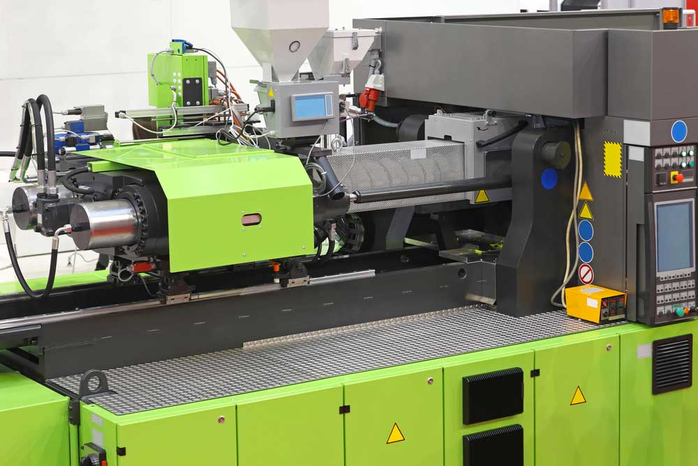
To achieve the cable assembly overmolding process, you must push the material into the mold cavity, exposing it to excess pressure. The most common material used in overmolds is thermoplastic. There’s some storage space for resin in the injection molding machine. The material is often delivered in a screw-type plunger enclosed in a metal tube (barrel) or an injection ram after the heating elements are equipped into the barrel to heat the resin to molten form.
First, push the resin into the healing barrel of the molding machine at the hopper end. It mixes using any colorants and transits the barrel’s length to the actual mold, where the colorant mixture and resin get pushed into the mold cavities. Finally, the material cools, imitating any designed features in the mold, including part numbers, trade names, and logos.
Injection molding machine
Overmolding Design Considerations
During the cable assembly design process, engineers use overmolding to provide bend and strain relief. For instance, they may use grommets as part of the assembly for any points that require installing through an opening and as a shield for the connector backshells protecting the contacts and termination points. Due to the increase in complexity tooling and the variety of materials you can use, any components that are to be injection molded should be carefully designed.
Cable Overmold Tooling Materials
Thanks to 3D printing, you can now use photopolymers for simple injection molds. Photopolymers enable the molding of resins at lower temperatures for a limited number of molding cycles.
Manufacturers categorize Injection molding machines according to tonnage. Tonnage defines the amount of force the machine uses to keep the mold closed during the injection process. Therefore, the larger the injection machine, the more cargo it exerts, producing more molded parts.
A die or mold is a tool manufacturers use to make the molded part. Molds are costly. Also, the more detailed and complex the mold, the higher the costs. Depending on the number of cycles to which you expose a mold, you can use different materials. And if you expect a mold to undergo thousands of mold cycles, then hardened steel is the ideal metal choice.
Because they’re made of the most robust material, hardened steel molds are costly. However, it’s a fair price, considering the mold’s prolonged lifespan and ability to withstand many cycles without wearing out quickly. Manufacturers often use steel molds in mass-production environments.
For molds likely to undergo several cycles, aluminum is a common choice. Aluminum serves a shorter period, but its malleability results in lower tool fabrication costs. Often, manufacturers produce molds using Computer Numeric Control machines or electrical discharge machining processes.
The material you intend to use on the molding itself will steer you in the right direction as to the material to use for the molds. If you plan on using thermoplastic resin, you can use aluminum or stainless/hardened steel. However, if the material is a liquid injection type, such as silicone, use molding tools made of hardened steel. When looking to accomplish a liquid injection, the tooling must produce exact measurements to avoid any gaps or secs that could allow the liquid to escape.
Before implementing various applications, designers often create 3D-printed models of the overmold to test the design’s fit and form. That helps avoid using costly hard tooling that could lead to the wrong results, which, should it happen, it’s impossible to alter the tooling.
Single or Multiple Cavity Designs
When designing molding, you can choose between single or multiple cavities. Each cavity is identical to produce multiple molds in a single mold cycle with a multi-cavity mold. Some designs create multiple nonidentical cavities. A common issue is ensuring the resin flows into different designs without creating air gaps or voids.
Manufacturers deliver resin material into the heated barrel through the hopper during molding. After the heat and forces of the screw, the material softens, and the mixed resin gets pushed toward the mold tooling. Manufacturers refer to the resin that accumulates at the end of the barrel as a shot at the point. A shot is the amount of resin required to fill a cavity, which also includes an extra amount to compensate for the anticipated shrinking of the resin. Cavities typically take seconds to fill up.
Then the ram or injection screw applies pressure on the shot until the resin at the gate to the cavity cools and solidifies. The gates to the cavity are the smallest part of the mold tooling. Therefore, it’s the first area to solidify completely. Once the resin at the gate hardens, the injection molding machine cycles and prepares another shot while waiting for the next molding cycle. The resin in the cavity keeps cooling, and you can remove it once it solidifies.
Oil or water gets circulated through the mold tooling in a series of channels to help the cooling process. Once the resin solidifies, the mold opens, removing the complete mold. Manufacturers use metal fingers or pans to make removing the mold in the mold tooling easier. And once they remove the mold from the cavity, the cycle begins again.
Pre-Mold and Overmold Designs
Some designs require that the mold comprise two parts; an overmold and pre mold. The pre-mold can consist of machine parts (pins or screws) or previously molded smaller parts. Normally, you will place these various parts in the cavity while the mold is empty. Then when the overmold cycles, the resin flows and then gets solidified.
Manufacturers often use this process when the overmold needs screws to fasten the connector to other installation components.
The Appearance of the Finished Product
After the molding process, the end product will always have blemishes and marks. Some of the reasons the molding process leaves marks to include:
The ejector pins touch the resin when pushing it out of the mold cavity.
Dimensional differences among the pieces of mold tooling.
Marks where the resin entered through the gate.
Mold tooling exhibiting signs of wear.
Blemishes and marks are inevitable. However, you can minimize the effects by specifying tight dimensional tolerance as you design the mold tooling and place gets in positions of the cavity that are not so noticeable. It’s important to consider the above factors when designing molding tools.
Injection Screw
Conclusion:
Custom-molded cable assemblies are robust and reliable, making them a common choice in various industries today. Most applications use molded cable assemblies to protect and interconnect cable assemblies. Feel free to contact Cloom Tech for the best custom-molded cable assembly solutions.
All arms of the Department of Defense, be it the Navy, Coast Guard, Marine, or Army, need precise control and reliable power. Thus, cable assembly military design forms the core of every piece of equipment used, armored vehicles, tanks, infantry vehicles, mine protection vehicles, ships, humvees, armored personnel carriers, SUVs, cargo vehicles, rugged ATVs, and four-wheel drive vehicles.
What Are Military Cable Assemblies?
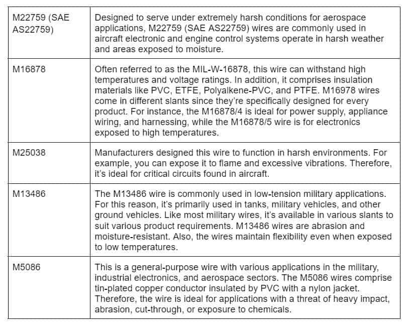
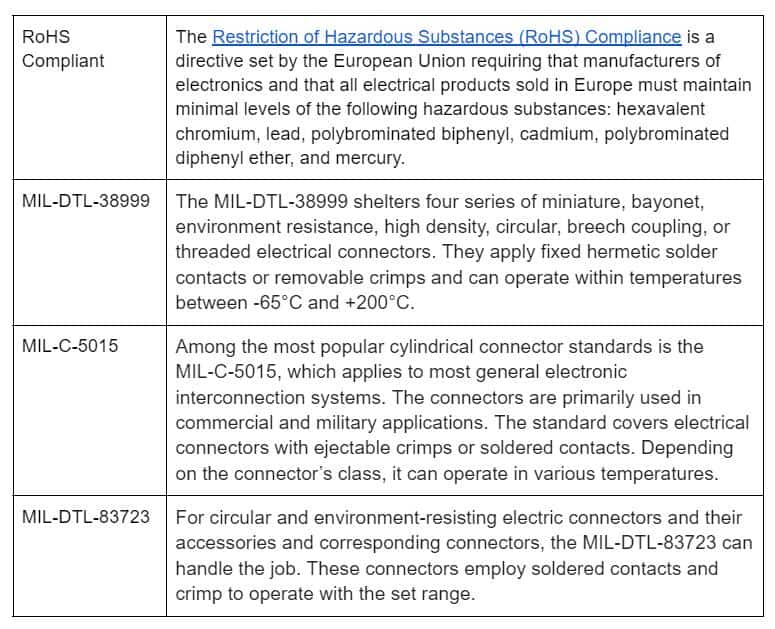
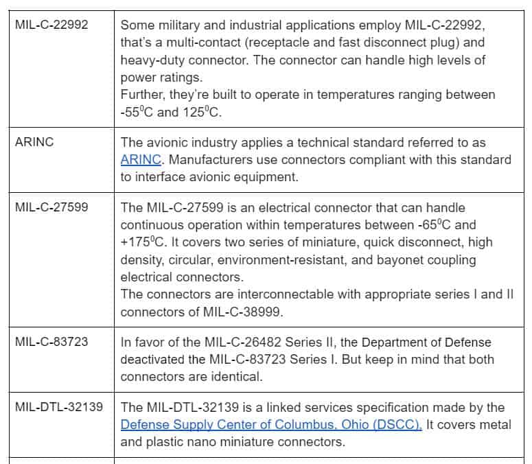
Manufacturers design and engineer military wire harnesses and cable assemblies to meet certain MIL-SPEC specifications. Also, they must fabricate the cable assemblies using connectors, wires, terminations, cables, and other components approved and specified for military application.
Standard wire and cable configurations will do the trick for most everyday applications. But due to the harsh conditions in aerospace and military applications, you’ll need configurations of higher quality and reliability.
Today, the primary use of military wire guidelines is differentiating wire and cable assemblies. Some references were successfully transitioned to standards by private entities such as ANSI, NEMA, and SAE. Therefore, manufacturers should refer to the standards before deciding on the construction cables and wires or materials for specific military-grade applications.
MIL-SPEC Wire & Cables
MIL-SPEC wires and cables are unique since they have their designation, unlike other products like high-temperature or hook-up wire. Like CSA and UL standards, people consider the product genuine or an actual MIL-SPEC wire by following a specific set of standards.
The wires get used in every military vehicle’s internal wiring of electric panels, electrical equipment, meter, and electrical components. The specific applications vary from antennas, airframe wiring, point-to-point wiring, bonding moving parts, and any instances that require durable shielding.
Today, manufacturers use several standards to differentiate a wire’s specific attributes. For example,
MIL-SPEC Connectors
MIL-SPEC connectors are shell-type connectors built to meet certain military specifications. When designing MIL-SPEC connectors, manufacturers considered the need to protect connections from harsh environmental conditions, making them usable in aerospace and military applications.
A connector consists of a plug, receptacle, and mating pair, each with a socket and pin contact. Usually, electrical connections consist of phosphor bronze or beryllium copper that’s later plated with gold or other non-corrosive high-conductive metal. However, manufacturers plug the connectors with a protruding ferrule holding the fibers for fiber-optic connections while also aligning two fibers for mating. With fiber optic connections, an essential specification is the insertion loss; that’s the amount of light lost during the connection.
Some of the military standards and specifications that MIL-SPEC connectors must meet include
Benefits of Military Cable Assemblies
Because of how much aerospace, military, and security technologies get exposed to extreme conditions, reliable custom cable assemblies and electrical wiring is needed to ensure safe and dependable equipment operation. Therefore, the connectors and cables share the following characteristics.
Ruggedisation
Connectors and cables meet various military-grade specifications. So they can handle medium and high-temperature installations for optimum performance even when exposed to extreme mechanical stress. Also, they’re suitable for high-frequency electronic applications where high temperatures pose a threat. In addition, MIL-SPEC cables offer outstanding, steady electrical characteristics with minimum power loss.
Miniaturization
The demand for miniaturization is increasing rapidly in the aerospace, military, and security industries. Miniaturized connectors and cables are equally efficient and reliable as conventional methods, only much lighter and smaller, offering better flexibility, easier integration, and shorter time delays for faster signals. Additionally, miniaturization makes integrating extra space for crucial aerospace and military applications easier.
Microwave & RF
A wide array of coaxial connectors enable the design of custom and high-performance military and aerospace cable assemblies. Standard core ranges cover a maximum frequency range of 4GHz to 40GHz. But if needed, specialized RF and microwave products can handle frequencies as high as 110GHz.
Applications of Military Cable Assemblies
Military and aerospace wire and cable assemblies enable dependable and safe operation for various critical applications, such as
Space force systems
Military ground components
Avionics systems
EMI-sensitive equipment
Field and inter-shelter communication components
Satellites and space shuttles
Ships, submersibles, and other marine systems
Airborne communication and navigation systems
Remote weapons control
5 Primary Factors That Help You Determine If you Need a MIL-SPEC Cable Assembly
Although you won’t always have to adhere to military specifications in every project, applying MIL-SPEC in some circumstances is useful. In addition, military-specified cable assemblies are more costly. Therefore, deciding whether it’s crucial to your application is important.
Are you planning on using it in a critical process? If this component’s failure threatens the entire process, it’s advisable to invest in a military-specified cable assembly that guarantees optimum durability and continuity of the process.
Next, consider the environment surrounding the cable assembly. Manufacturers design MIL-SPEC cable assemblies to withstand harsh conditions without malfunctioning. The cable assemblies can undergo extreme temperatures while offering corrosion and abrasion resistance. If your intended application demands high levels of robustness, then MIL-SPEC cable assemblies will effectively handle the job.
Consider the impact of vibrations and motions. If the intended application exposes components to constant vibrations and motion, you should consider getting military-specified cable assemblies. Especially in military applications where there are frequent motions and constant vibrations due to the travel of tricky terrain, MIL-SPEC cable assemblies are a must-have. Therefore, if your intended application poses similar conditions, it’s best to opt for MIL-SPEC cable assemblies.
Is EMI/RFI radiation an issue? Unless radiation is necessary, such as in radio jamming, you should avoid exposing your application to such radiation. Consider getting MIL-SPEC cable assemblies. These offer complete RFI/EMI shielding, which is especially vital in various applications.
Are you complying with the industry regulations and requirements? Some applications require MIL-SPEC cable assemblies to get the best out of equipment. Also, this could ensure product reliability and safety compliance.
Conclusion:
Manufacturers designed the MIL-SPEC cable assembly according to military standards and specifications. Often, they employ specially designed and durable materials in these cables.
Such materials make the cable assembly more resilient in several situations, such as when exposed to high vibrations. For aerospace and military applications, you need reliable and high-quality wire harnesses and cable assemblies for the best result. At Cloom Tech, our team of experts design and fabricate MIL-SPEC cable assemblies to better serve your needs.
Are you working on a project requiring a braided wire harness? It’s understandable with so many braided wire harness options. Here’s some information to help you make a more informed decision.
What are braided cable sleeves?
Often referred to as a protection sleeve, a braided cable sleeve serves as a cable protector and organizer.
Braided sleeves offer an open weave. Unlike typical cable protection options made of smooth and unbroken metal or plastic, an open weave has several advantages, such as quicker moisture evaporation, easier heat dissipation, maximum flexibility, and easier inspection in case of suspected damage. Also, braided sleeves provide better durability and dependability.
All in all, their unique design allows for special functions like fire prevention. Therefore, they offer exceptional protection for wires exposed to extreme industrial environments.
Caption: Braided cable color options
Benefits of Using Braided Cable Sleeves
They have proven advantageous, especially for commercial and industrial applications.
Flexibility:
As previously mentioned, braided sleeves provide superior flexibility compared to other alternatives like metal conduits. For example, braided sleeves can fit through compact spaces, change to different sizes and shapes, and find their way around complex equipment designs.
Constriction Around Irregular Shapes:
Braided sleeves can constrict around irregular cable shapes thanks to their flexibility. That way, they provide protection and cushioning without creating space that could allow the collection of moisture.
Better Organization:
Braided sleeves group numerous wires in a compact and neat sheath, making the design more appealing. In addition, braided sleeves enable quicker identification of specific wires.
Damage Resistance:
Their strong design enables them to withstand increased mechanical stress, abrasion, and cuts.
Extra Cushioning:
Braided sleeves have some extra cushioning in their design to protect the wires from shock damage, especially in cases where heavy impact and countless vibrations are unavoidable.
Moisture Draining:
Water can constrict around the cables. The open-end weave allows for easy slip-through of water, preventing moisture damage.
Effective Heat Transfer:
Their open weave design also enables heat transfer. Any built-up heat around the cables can easily dissipate, preventing potential issues or electrical fires.
Expansion capabilities:
Interestingly, braided wire harnesses have remarkable expansion capabilities, which come in handy, especially for large-sized cables that would not ideally fit in a more rigid form of protection.
Materials Used in Braided Cable Sleeves
You have several material options for braided sleeves.
Nylon
The most common material used in braided sleeves is nylon. That’s especially because of its flexibility and lightness. Such capabilities allow for easier installation and adjustment for specific needs and requirements, such as the automotive wiring harness industry.
Also, nylon sleeves can easily conform to various shapes and sizes, offering complete protection in cases with wires of different shadows or sizes.
Moreover, nylon is very effective at preventing the accumulation of moisture.
Since nylon protects from various environmental factors, it’s an industry favorite. However, it’s important to note that nylon is less stable when exposed to high temperatures and has limited UV radiation, corrosion, and chemical resistance than other options.
Polyester
The protection is exceptional.
It’s very flexible and can expand almost three times the original size. Thus, it allows for close fitting around irregular-shaped and oversized cables.
Also, extreme resistance to high temperatures and corrosion makes polyester an industry-favorite material, especially for automotive and electronics applications.
However, polyester sleeves exhibit lower stability under immensely extreme temperatures and limited UV and chemical resistance.
Polyethylene Terephthalate (PET)
Polyethylene terephthalate is a category of polyester that offers flexibility and is lightweight, like nylon.
PET sleeves are easy to install as they easily adapt to various shapes to serve various purposes.
Also, PET has extreme fluid and water resistance. It’s an ideal option for applications that subject cables to automotive fluids (engine fluids and gas) and cleaning chemicals.
Further, because the material has remarkable resistance to extreme temperatures, impact, UV light, and abrasion, PET sleeves help ease the strain on stretched cables, averting any breaking or cracking. Hence, PET sleeves can increase the lifespan of the cables.
Moreover, PET is unique for its exceptional high expansion rate of about three times the original size. This quality allows it to fit over cables with irregular shapes easily.
Because Polyethylene terephthalate allows you various options, it’s best to explore your choices to ensure you find the best fit for the task.
Polyphenylene Sulfide (PPS) Monofilaments
Polyphenylene sulfide monofilaments are among the lightest braided sleeves. However, this should not deter you from using them, as PPS can withstand chemicals and solvents very well. It’s inert to acids, fuels, steam, and strong bases, making it the ideal material for applications involving exposure to such substances.
Also, PPS is flame-resistant.
Additionally, PPS is ideal for specific applications, such as aerospace and telecommunications industries, because it’s moisture and chemical resistant and can withstand high temperatures.
On the downside, PPS has lower flexibility capabilities and provides limited corrosion resistance and UV light protection.
Nomex
It is another lightweight material.
It’s also very expandable and has heat and flame resistance. It has a notably higher melting point.
This material also protects against moisture, chemicals, abrasion, radiation (gamma, beta, and X-rays), and solvents. It offers resistance against various acids.
However, Nomex has lower flexibility capabilities and offers limited UV light protection and corrosion resistance.
Where to Use Braided Cable Sleeves
Some industries using braided sleeves include:
Marine:
Interestingly, braided sleeves are popular in the marine industry thanks to their exemplary performance in water and most fluids. These industries use them primarily in control panels, vessel engines, and switchboards.
Automotive:
Because of their exceptional resistance capabilities against abrasion and engine fluids, braided sleeves have wide use in the automotive industry, primarily around the vehicle’s electronic system.
Military:
Military applications often expose cables to harsh environmental conditions, making braided sleeves an excellent solution. They use them primarily in transport vehicles.
The automation and robotics industry requires precision and flexibility; hence braided sleeves are the first choice.
Manufacturing:
Manufacturing equipment is often exposed to increased operational stress and harsh conditions. Braided sleeves are ideal for such situations because of their durability, expandability, and high resistance to several factors.
Power Generation:
The power generation industry heavily relies on properly functioning cables. Braided sleeves offer a great solution here as they provide flexibility and protection from UV light, moisture, heat, wind, and dust, especially in outdoor applications.
Rail Transportation:
The rail transportation industry utilizes braided sleeves to protect cables hanging from the undercarriages constantly exposed to vibrations, harsh element conditions, abrasion, and high temperatures.
Mining and Heavy Construction:
The equipment and machinery used in mining and construction are constantly exposed to dust, extreme temperatures, UV radiation, fluids, chemicals, moisture, vibrations, and collision. Hence the use of braided sleeves, as they resist such factors.
Different Types of Braided Sleeving
Below are different types of braided sleeving.
General-Purpose Sleeving
For projects where the main concerns are durability and easy application, general-purpose sleeving is an excellent solution. This method is easily adaptable because of its expandability and side entry, ensuring the integrity needed for resistance and durability.
Additionally, this sleeving’s expanding capabilities simplify the application since the sliding cables through the sleeving is simple and efficient. Further, the sleeving can contract, enabling cohesive wire harnesses, despite any inconsistencies in the size of cables.
You might opt for tight weave options if you want increased abrasion resistance. For situations where disrupting the wire of the hose connection is out of the question, you could opt for side entry sleeving. And for reapplication or installation processes, wrap-around sleeving will do the trick.
Heavy Duty Sleeving
Heavy-duty sleeving offers excellent protection, which is necessary for battling extremely rigorous conditions. This sleeve option is highly cut and capable of resisting abrasion and heat, ensuring that it does not melt, burn, or support combustion.
Also, heavy-duty sleeves are flexible while maintaining the integrity needed to protect components exposed to a harsh environment adequately. For example, this braided sleeving type can resist bases, fuels, acids, solvents, and salt, preventing any compromises in the hose functions. Additionally, it’s capable of deflecting and containing hose ruptures.
Braided Metal Sleeving
With braided metal sleeving, you get abrasion and cut resistance. Such properties make this sleeving ideal for high-intensity weather, grounding solutions, and where temperature resistance is necessary.
Caption: Metal Braided Sleeve
Additionally, metal sleeving has exceptional durability and offers RFI, EFI, ESD, and UV resistance. And some have germicidal and antimicrobial properties. Further, braided metal sleeving is flexible, uniquely functional, aesthetically pleasing, and durable, making it ideal for outdoor, aerospace, and automotive applications.
Remember, it’s best to use virtually indestructible sleeving options, such as stainless steel sleeves, for more demanding projects. Doing so ensures that all the exposed wires are safely tucked in and the project remains rust-free and aesthetically pleasing.
Flame Retardant Sleeving
Flame-retardant sleeving offers a similar solution to a general-purpose one, plus the added benefit of flame prevention. This added property is ideal for automotive, engineering, electrical, and several applications vulnerable to the threat of fire damage. Flame-retardant sleeving mitigates the threat of a flame sparking.
Advanced Engineering Sleeving
It offers the most technologically advanced materials with capabilities that satisfy the most challenging applications while remaining lightweight and pliable.
Also, it has moisture, chemical, abrasion, and temperature resistance and easy application and bacterial growth resistance.
High-Temperature Sleeving
As the name suggests, high-temperature sleeving is highly resistant to extreme temperatures. It not only can withstand extremely high temperatures but also low temperatures, resisting common solvents and chemicals.
Installing it is a straightforward process, making it ideal for automotive, engineering, and aerospace applications. High-temperature sleeving contains a silica and fiberglass composition that ensures your cables remain cool in temperatures up to 20000F.
Specialty Sleeving
With specialty sleeving, you can handle very specific braided sleeving tasks. It offers options that are easy to edit out of video production, plus noise reduction.
Also, it’s remarkably reflective. Even bright white comes nowhere close, as specialty sleeving is almost 1,500 times more reflective. Additionally, its sleeving is adequately slim, an added advantage for micro-optics.
Further, specialty sleeving makes wires and cables less vulnerable without affecting the project.
Automotive Sleeving
If you’re searching for something with adequate temperature and abrasion resistance required to withstand high-performance automotive conditions, look no further than automotive sleeving.
That’s because automotive sleeving offers noise reduction, abrasion and temperature resistance, penetration protection, and nonconductivity.
Choosing the Correct Cable Sleeve Size
For sleeves to serve their purpose properly, they must be the correct size. Below are steps to guide you in picking the right size.
First, measure the diameter of the cable.
Next, determine the fit. You could pick between a snug and loose fit. Remember that a loose fit allows for flexibility, while a snug fit gives extra cushioning.
After that, you’ll need to determine your sleeve diameter. If you opt for a loose fit, you’ll need a diameter larger than the cable diameter. On the other hand, the diameter should be smaller than the cable diameter for a snug fit.
Lastly, follow up by adding a bit of length for the sleeve because they contract when stretched in diameter. A few extra millimeters should do the trick.
Managing Braided Cable Sleeve Ends
When using braided sleeves, you must maintain your sleeve frequently to avoid them unraveling at work. To manage the ends, you’ll have to terminate them using one of the following methods:
You could use tape because it’s a cost-effective and efficient method of managing sleeve ends. You’ll need to tightly enclose the ends once you’ve inserted the cable wrap. For aesthetic purposes, you might choose matching tape and braid sleeve color. However, as much as tape provides an economical and simple way to manage sleeve ends, removing the tape is often difficult. You cannot recycle.
Another quick and effective method of managing sleeve ends is using cable warps. Cable wraps neatly slide onto the sleeve ends, tightly securing them. Additionally, cable wraps easily come off, and you can reuse them.
The final method is using heat-shrinking tubing. This method is more secure but takes time to apply properly. You’ll need to slide the plastic tubing through the cable and apply heat via a heat gun or blow torch. The most common application is in aviation and automotive applications.
Braided Loom Vs. Convoluted Tubing
Convoluted tubing is another popular option. The two technologies both give you pros and cons.
Pros
Braided Technology
When you pass the wire harness through the looming machine, you wrap it in braided PVC-coated nylon that ensures flexible protection from vibrations and heat.
A braided loom allows the passage of moisture into the machine, especially when it’s exposed to freezing conditions.
Nylon is directly braided into the wire harness, creating a clean look free of extra zip ties or tape.
Braided technology offers a wide variety of colors that add to the appeal and uniqueness of your brand. If black is your preferred choice, you could opt for tracers that are different colored strands woven into the braid. Tracers help the OEM determine the wire harness supplier and the color code the harness applies.
Braided loom increases the lifespan of your harness by providing tightly bound assemblies, offering 100% loading, reducing deterioration and insulation wear, and significantly reducing wire-to-wire movement. Tightly bound assemblies avert the entry of abrasive materials, avoiding damage to the wire insulation. Also, to prevent any harm from moisture to the insulated wires, the braided harness has small holes or openings that enable air and moisture to pass through rather than accumulate. Additionally, the air spaces of the braided wire harness assembly provide improved heat resistance, increasing the lifespan of your harness. Braided harness protection typically lasts 10 to 13 years.
Convoluted Tubing
Convoluted tubing offers various plastic options with varying heat and chemical ratings.
Convoluted tubing is liquid-tight and capable of accommodating a variety of connector backshells.
The various fittings available for various branch configurations maintain the liquid-tight seal.
With convoluted tubing, you have a wide array of diameters that enable flexibility of the harness. Also, colored tubing is an option to fit your brand and aesthetic specifications.
Cons
Braided Technology
You’ll need to tape the wires together neatly while separating the different branches.
You require a machine capable of handling the wire harness size, which could be labor-intensive. In addition, the laborers must take frequent breaks to avoid neck, shoulder, and back strain.
The equipment poses a noise pollution threat that requires workers to wear headgear for protection.
Convoluted Tubing
Covering the harness with convoluted tubing allows the tubing some 20 to 30% free airspace. The free airspace ensures there’s room for wires to move around during vibrations from the equipment moving around. However, it also accumulates dirt and particles, leading to potential damage. Over time the deterioration of the tubing could expose the conductor, resulting in electrical failure. Also, the small airspace leaves minimal room for breathability, allowing engine fluids to accumulate, which could cause erosion of the tubing and insulation in the long run.
Convoluted tubing doesn’t provide thermal protection, especially in extremely high or low temperatures, which could lead to the failure of the harness protective layer. It’s no wonder convoluted tubing protection typically lasts two to four years.
You’ll have to fish the harness through the tubing and fittings, which could prove problematic if the design is complex. Further, it would help if you used fittings at branch intersections, zip ties, or electrical tape to secure the tubing since every branch needs a separate piece.
Similar to the braided technology, you’ll need to use tape to neatly group the wires in different branches before attempting to fish the harness through the tubing.
Caption: Convoluted tubing
Conclusion:
Braided cable sleeves protect cables and wires used for industrial purposes from especially heat, corrosion, chemicals, abrasion, electromechanical waves, and moisture. And there’s a wide range of options available. These sleeves vary in size and material type to cater to all kinds of use, general to industrial. For all your cable assembly inquiries and needs, feel free to contact Cloom Tech, and our team of professionals will handle the task.