Micro USB Cable – The Ultimate Guide On How To Choose

USB Cables

If you are using a cable to connect or charge mobile and compact gadgets like mp3 players, smartphones, cameras, printers, or GPS devices, then most probably, you are using a micro USB cable.

Micro USB cables can be of different types.

With the many choices out there, it’s common to get confused with many things to consider.

How do you know which micro USB cable to use with different gadgets, and what are the types?

In this guide, we will tell you all you need to know about USB micro cables so that you can always pick the right cable for your purpose.

Chapter 1 – What is a Micro USB Cable?
USB Cable

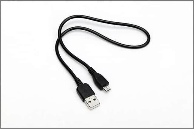
A micro USB cable is the smallest form type of the  Universal Serial Bus (USB) and comes with two connection types and USB 3.0.

Micro USB cables provide a convenient means to connect various devices and plug them into your chargers.

Micro USB cables are useful for devices where you cannot use standard or Mini USB connection ports because of their size or usability.

All micro USB cables provide the same performance as you would expect from a standard-size USB cable.

In the next chapter, we will discuss the market’s different types of micro USB cables.

Chapter2:Micro USB types

Micro USB A

The micro USB-A is a compact connector in a trapezium shape. Measuring 6.85mm in width and 1.8mm in height, the connector has slanted edges that allow easy orientation while plugging the cable. The connector transmits electric and data signals with the help of five pins: Vcc, D+, D-, ID and Ground. The VCC and Ground can supply a 5 Volts DC supply while Data +/- transmits data signals. ID helps in mode detection.

The following table gives you complete information about the micro-USB A connector.

PINNAMEWire colorFunction 
1VccRed+5 volts
2D-WhiteData negative
3D+GreenData positive
4IDN/AMode detection
5GroundBlackSignal ground

Micro USB B:

The structure and shape of the micro-USB B are similar to Micro USB A, featuring a trapezium shape with a slanted top and bottom. Like micro USB A, this shape allows the connector to orient easily while you plug the cable. The PIN in micro USB B is also five, but the shape and size of the pins differ from that of micro  USB A. You can use this connector for data transmission and charging compacted devices like mobile phones.

The following table gives you complete information about the Micro USB B connector.

PINNAMEWire ColorFunction 
1VccRed+5 volts
2D_WhiteData negative
3D+GreenData Positive
4IDN/AMarker pin for OTG devices
5GroundBlackSignal Ground

Micro B 3.0:

Micro B 3.0, a superspeed version of Micro USB B, has ten pins. These extra pins enable it to transfer data at high speed, manage power effectively and make it compatible with larger devices.

Popularly called SuperSpeed USB, this micro-B 3.0 shows backward compatibility with old USB standards. However, you must know that USB 3.0 is incompatible with all devices. If you want to use this superspeed USB 3.0, the computer port and the device must be compatible with the new standard.

The following table gives you complete information about the micro-USB 3.0 connector.

PinNameCable colorFunction
1VCCRed+5 volts DC
2D-WhiteData negative
3D+Green Data positive
4IDDark BlueMode detection
5GNDBlackGround signal
6USB3 SSTX-BlueSuperspeed transmit positive
7USB3 SSTX+YellowSuperspeed transmit negative
8GNDNot ApplicableGround signal (return)
9USB3 SSRX-PurpleSuperSpeed receive negative
10USB3 SSRX+OrangeSuperSpeed receive positive

Important information:

  • Port: This is the place where USB cable plugs into
  • Type: It defines the shape of the connector or the port
  • Version: It defines the technology allowing data transfer along the cable.

Chapter 3 – Types of Micro USB Cables

Before diving into the types of micro USB cables, let’s learn a bit about the USB connection standard.

USB cables were introduced in 1994 by some tech companies to provide a unified connection standard for transferring data and electricity.

These cables are widely used today for different devices and come in different generations, like USB 1.0, USB 2.0, and USB 3.0.

The USB 1.0 and 1.1 can transfer data at 12 Mbps, mostly outdated.

USB 2.0 is the most popular cable, capable of achieving 480 Mbps transfer speeds.

The USB 3.0 can clock 5 Gbps, while the newer USB 3.1 can reach 10 Gbps data speeds.

USB cables feature forward and backward-compatible technology, which means you can use the cables irrespective of their generation (USB 2.0 or USB 3.0) as long as the connectors are the same.

The cables will automatically adopt the lowest USB standard when using cross-generation devices.

Micro USB cables are also classified into USB-A, USB-B, and USB-C types and feature different connectors.

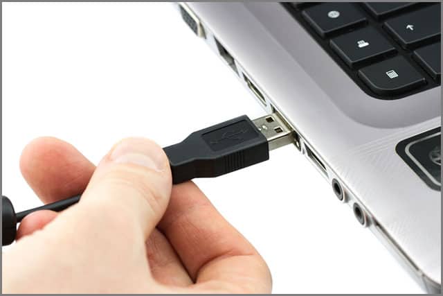
You can differentiate the cables with your eyes, but you can’t tell whether it’s a USB 2.0 or USB 3.0 just by looking.
USB Cable

The Common Types of Micro USB Cables Out There for You to Choose From

Here are the common types of micro USB cables-

1. Micro-A USB Cables

On-the-go (OTG) devices commonly use the Micro-A USB cable and differ from the normal USB connection.

You can establish communication between two devices using Micro-A USB without a computer acting as a mediator.

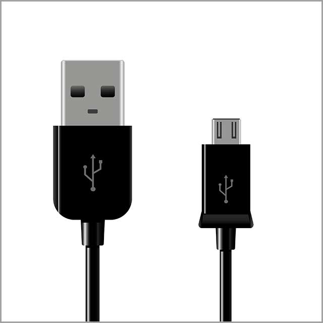
Micro-A USB cables come with a female, rectangular-sized connector.

You can easily identify a Micro-A USB cable by looking at its compact 5-pin design and white receptacle.

Micro-A USB cables often are compatible for use in conjunction with Micro-B USB gadgets.

The OTG devices normally have a Micro-AB socket, which provides ports for supporting both connection types.
Micro USB Cable

2. Micro-B USB Cable

The Micro-B USB standard is in most smartphones and small electronic gadgets.

There’s no difference between USB 1.1 and USB 2.0 in the Micro-B ports case; they look the same.

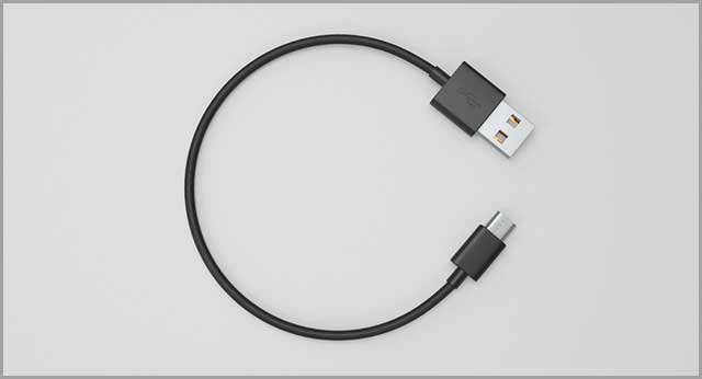
The Micro-B USB cable is available with both male and female connectors, so you can use devices using different connection types.

Generally, you will see a female connector on smartphones, whereas the cable comes with a male connector.

Micro-B USB connectors appear like a half-hexagon in shape, as the ports and connectors feature tapered edges.

Generally, the cables have a black-colored receptacle and portable 5-pin design.
Micro USB Cable

3. USB 3.0 Cables

USB 3.0 cables can be compatible with both Micro-A and Micro-B USB ports.

The cable connector size of USB 3.0 is a bit bigger than USB 1.0 and USB 2.0 standards and is suitable for handling the high transfer speed of USB 3.0.

Remember that Micro-A and Micro-B don’t use the same connection standards.

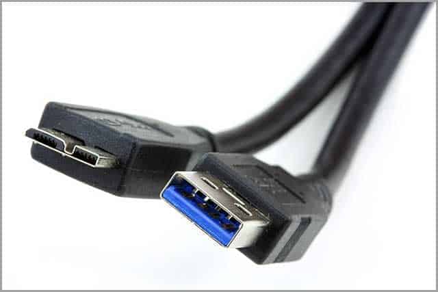
The new generation of USB 3.0 standards presents a double-socket connection port.

USB 3.0 devices generally use a cable divided into two connectors to ensure backward compatibility.

You can use one connector for older Micro-A or Micro-B cables, while the other is reserved only for USB 3.0 connections.

Many new smartphones have started using USB 3.0 as it offers a 10 times performance increase compared to USB 2.0.

You can also use improved power efficiency and additional features like USB streams to leverage data throughput for storage devices.

Smartphones using USB 3.0 generally have dual-mode device connections.

The functionality enables you to use the single port as a peripheral port while also playing the part of a host port.

Now that you know about different micro USB cables, let’s learn more about their applications.
Micro USB Cable

Chapter 4 – Micro USB Application Options

You can use micro USB cables for a wide range of applications.

Can you even find a micro USB to HDMI cable to directly access all your favorite videos and movies?

Please keep reading to learn more about micro USB cables and their applications.

1. Micro USB to HDMI Cable

Tablets and phones have displays to help you watch movies, play games, or see videos.

But for many people, the screen size is too small, and they need something bigger!

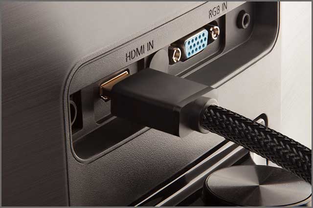
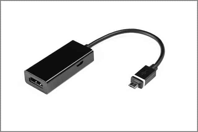
Micro USB to HDMI cables enable you to connect MHL-enabled tablets and smartphones with TVs or other display devices using the HDMI port.

It is a convenient and cheap method and doesn’t need you to get lost in a mess of cables.

The micro USB to HDMI uses the micro USB port of your tablet or smartphone and passes the signal to the adapter, which converts it to HDMI format to connect with your TV.

If your TV doesn’t support MHL, you must connect a USB power cable to the converter, which provides a charge to your phone or tablet.

You can use your TV display to play games, browse the internet, watch movies in HD, see photos, and more.

The micro USB to HDMI cable supports both video and audio.

The recent standard of MHL can provide 8-channel surround sound and even play videos at 4K resolutions.

Older versions can support 1080p video formats with 7.1-channel digital audio.

Before buying the micro USB to HDMI cable, you should check if your tablet or phone is compatible with MHL.
Micro USB Cable

2. Micro USB Extension Cable

Do you find the length of your micro USB cable too short? 

Can’t charge your phone sitting on your couch as the cable doesn’t reach the wall power outlet?

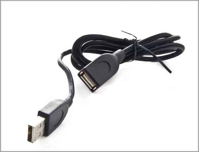
Using a micro USB extension cable, you can resolve your problems in an instant.

The extra length of cable serves as an extension between devices or cables and helps you cover more area than you can with a single cable.

The extension cables have a micro USB male port and a micro USB female port.

The extension cables can support USB 2.0 or USB 3.0, so you should consider your data transfer needs before choosing one.

The connectors at the end of the micro USB cables also vary.

You can find micro-A ports, micro-B ports, and some newer versions that also come with a Type-C port.

So, checking the ports of the devices you want to connect is necessary before buying a micro USB extension cable.

Some solar panels also use micro USB cables; the extension cords can help establish connections over increased distances.
Micro USB Cable

3. Micro USB to Micro USB Cable

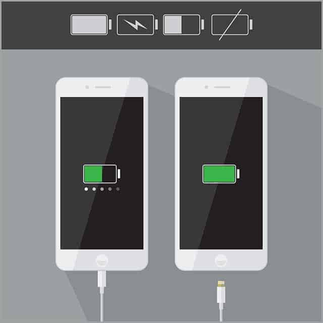
Micro USB to micro USB cables connect two devices to transfer data or power.

For example, you can connect two tablets, one tablet, and a smartphone or two smartphones to exchange data or charge the device.

Micro USB to micro USB cables have micro USB ports at both ends.

One end of the cable is generally labeled as “Host,” which you need to plug into the controller device.

The cable carries power from the controller device at the host end to the other device, while you can transfer data both ways.

The cables come in handy when you don’t have a charger nearby to emergency charge one device by sourcing power from another.

You can also establish a direct hardline connection between devices using the micro USB to micro USB cable and eliminate the need for extra adapters and lag in performance.

The device connected to the “Host” port must support On the Go (OTG) functionality.

Most Android smartphones and tablets are OTG compatible, so you can be sure your device can use micro USB to micro USB cables.

Micro USB to micro USB cables have a wide range of applications.

Besides connecting tablets and smartphones, you can connect external hard drives or SSDs to carry out the data read and write function.

You can hook up other accessories using a micro USB to a micro USB cable.

For example, cable connects keyboards, cameras, and controllers to your tablet and smartphone.

The accessories must have a micro USB port so that both devices can work without glitches.
Micro USB Cable

We have now discussed various types of micro USB cables like micro-A, micro-B, and USB 3.0.

Recently a new variant is available in the market called USB Type-C.

In the next chapter, we will discuss Type-C cables and find their difference from micro USB cables.

Chapter 5 – The Difference between Micro USB and USB Type-C

Are we looking to choose between a Micro USB and a USB Type C?

You aren’t alone – many make that choice each day.

While it was the former earlier, it is the choice for many these days.

We will take a look at why.

What is USB Type-C?

You can find USB Type-C in new smartphones, laptops, and tablets.

The new standard is slowly evolving to replace the older USB standards and even works for other technologies like Thunderbolt and DisplayPort.

USB Type-C features all the new improvements, and some smartphones have even replaced their 3.5mm audio jack with Type-C connectors.

Type-C also supports new USB standards like USB 3.1 to achieve higher transfer speeds and improve power delivery using the USB connection.

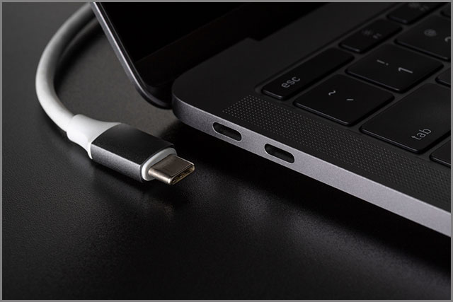
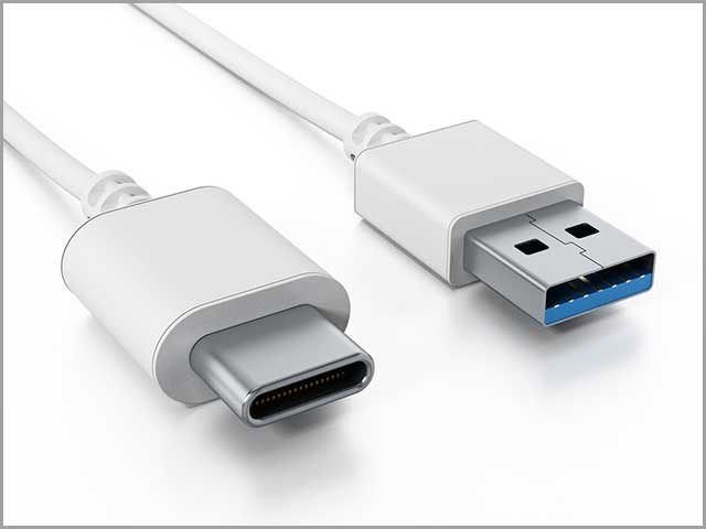
The USB Type-C cables have a new type of connector, similar in size to a micro USB connector.

USB standards have moved from 1.0 to 2.0, and now we have USB 3.0, but the connectors never changed.

USB Type-C introduces a new connector that meets the small needs of smaller and thinner devices available today.

You can also plug in a Type-C cable without checking its orientation, as it’s reversible.

Most of the current devices have been transformed into USB Type-C, to don’t need to carry around a bunch of different USB cables for different devices.

USB Type-C also improves the power delivery over older standards like USB 2.0, which can carry 2.5 watts of power.

Type-C increases this limit to 100 watts and uses a bi-directional technology to send or receive power while you can exchange data simultaneously.

Some new laptops like Google Chromebook Pixel and MacBook provide USB Type-C ports for charging.

In the future, all devices can switch to Type-C to make charging and transmitting data convenient.

Now, let’s check out the differences between micro USB and Type-C.
USB Cable

Micro USB cable VS USB Type-C cable

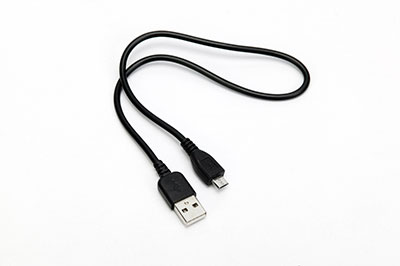
Micro USB cables generally have a micro-B USB connector at one end and a rectangular-shaped Type-A USB connector at the other.

Most micro USB cables use the USB 2.0 standard, while some new smartphones feature the USB 3.0 standard.

You can’t connect micro USB cables interchangeably, and they must fit in one way.

There are two hooks on the lower side of the connector to keep the cable in place.

Micro USB connectors were introduced as an industry standard to replace the proprietary connectors used by brands like Samsung and Nokia.

USB Type-C cables have a roundish, oblong-shaped connector, which promises to bring unity in the field of different connectors.

Though it looks bigger than the micro USB connector, it is more streamlined and compact.

The Type-C connector is reversible, which means you can connect it any way you want.

You don’t have to flip it numerous times to ensure the right side goes in!

USB Type-C connectors mostly use USB 3.0 and 3.1 standards, which means they can offer better performance than micro USB when it comes to data transfer speeds (5 Gbps to 10 Gbps).

It can also support up to 100 watts of electricity, enabling you to charge even your laptop or cameras.

Some manufacturers offer Type-C connectors but use USB 2.0 standards due to the low power requirements of smartphones or tablets.

USB Type-C can replace the old Type-A connectors in devices like tablets, smartphones, laptops, cameras, HDMI, game controllers, scanners, printers, and more.

USB Type-C is more versatile than micro USB and is not limited by design.
Micro USB Cable

Chapter 6:Micro USB Vs. Mini USB: What’s the difference?

Between the Micro USB and Mini USB, Mini USB is the earlier version. It was introduced as the first miniature form of USB in 2005. Roughly shaped as an anvil, the Mini USB connector has 5 pins. 

When it was introduced, it was used for Digicams, MP3 pliers, cell phones and various other devices. Due to its small size of 3mm by 7mm, it was widely accepted in the market. Further, its capability of connecting and disconnecting 5,000 times made it highly durable.

On the contrary, Micro USB was introduced in 2007 and displayed better functionality and more convenience than Mini USB. It has five pins, out of which the fifth one is the ID pin. It could function as both Type A and B connectors. On the other hand, the ID pin of the Mini USB offered no value.

Further, Micro USB has a round top with a flat bottom. Its size is smaller, i.e., 6.85mm by 1.8 mm, and 10,000 connect disconnect cycles.

Additionally, you can transfer data faster at 480Mbps with Micro USB. You can find micro-USB ports on various Android devices, tablets, phones, or other devices like GPS navigation devices, digicams, video game controllers, etc.

The best part of Micro USB is its capability to support USB OTG or USB On The Go. This feature allows tablets and phones to work as hosts for small devices like USB flash drives, mice, and keyboards.

So, with this, you can connect and use several devices with your tablet or smartphone. This option is not available in Mini USB.

With this comparison, it seems that Mini USB technology is useless and must be obsolete. However, some devices still use Mini USB ports and connectors.

Conclusion

Micro USB cables are still widely used to connect tablets and smartphones and charge devices worldwide.

We at Cloom Tech can help you know more about micro USB and the implications of manufacturing cables based on the standard.

Our expert and professional team caters to businesses of all sizes and helps them meet their custom micro USB needs.

We can deliver high-quality cables accurately matching the specifications of your wiring diagram with a quick turnover time.

Contact us as soon as possible for a private consultation to learn more.

Fan Relay Wiring: Your 5-minute Why and How-to Guide

radiator cooling fan

It is midday in summer, your car cooling fan is blowing, and then everything comes to a grinding halt.

What do you think might have happened? 

In most cases, the fault is terrible fan relay wiring.

Reading along, you will learn all about your vehicle’s cooling system.

In particular, you will find how necessary the fan relay wiring is to the system.

What is the Cooling Fan Relay?

Cooling fan wiring diagram

A cooling fan relay controls when the electric radiator cooling fan turns on and off.

It does so based on the temperature information from your car’s electronic control module or a thermostatically controlled sensor. 

For example, if the thermostatically controlled sensor measures an abnormal engine temperature, it signals the cooling fan relay to send a 12-Volt electric charge to power the fan.

Consequently, your radiator receives a constant gust of cool air bringing its temperature down.

Once the temperature drops below the threshold, your car’s electronic control module sends a new signal to the cooling fan relay instructing it to switch off the charge. 

However, you will find cars with electric cooling fans running after the engine shuts off. 

What common symptoms indicate you may need to replace the Cooling Fan Relay?

Old relays

Here are the typical signs that you need to replace your cooling fan relay:

  • Your engine temperature is higher than usual. It means the fan relay does not respond to the thermostatically controlled sensor or electric control module signals.
  • Your electric fan continues to run even after you turn off the ignition. Here, you may have a blockage within your fan relay system, causing the switch not to toggle between on and off.
  • Air-conditioning does not function. Some vehicles’ air conditioning compressor fans also use the fan relay to turn on and off. Consequently, they fail to turn on whenever there is a fault with the cooling fan relay system.

Where Do the Four Wires Of an Electric Fan Relay Go?

A relay without housing

Use our fan wiring diagram and guide to ensure you correctly wire your fans to your relay.

Before that, let’s have a clear picture of where the four wires of an electric fan relay go.

  • First, wire 85 connects the relay to the thermostatic switch, determining when the fan is operational. 
  • Secondly, wire 86 is the connection to your car’s ignition switch.
  • Third, Wire 87 connects to the electric fan’s positive wire.
  • Finally, wire 30 links to your car battery, requiring a constant 12-Volt current.

The wire insulation colors may vary depending on your electric fan relay kit supplier.

How to Wire an Electric Fan with A Relay?

The type of electric fan cooling system you use depends on your required cooling.

As such, you can opt for either single or dual cooling fans.

Additionally, the installation procedure may vary depending on your electric fan relay kit.  

Wiring a Single Cooling Fan.

  single electric fan

  single electric fan

  1.  First, remove your car’s stock mechanical fan and mount your electric fan onto your radiator.
  2.  Then, install the single relay where it is safe from excessive heat and water. Exposure to these elements can compromise the functionality of your new cooling system.
  3.  Next, connect each of the wires as per the wiring diagram. For example, wire 30 only connects to the fan’s positive terminal.
  4.  Finally, if all connections are correct, your engine should receive sufficient airflow to cool it.

Wiring Dual Cooling Fans.

Dual electric fans

Dual electric fans

The process of wiring double electric fan relay systems is similar.

However, the space available may cause you to make some adjustments.

For example, you can use a single activation fan relay for both fans.

However, doing so will require you to use a higher gauge connector wire and fuse a slightly higher amperage.

Below is the procedure for installing a dual-activation Fan Relay.

  1.  First, remove your car’s mechanical fan and mount the dual electric fans onto your radiator.
  2.  Secondly, install the activation fan relay kit in a heat- and moisture-free location. Depending on their required power, you can opt for a single activation fan relay for both fans. However, you will need a dual-activation fan relay if they draw more than 15 amps each. Cloom recommends the AR-79 with an amperage rating of 60 amps.
  3.  Next, install a 30-Amp fuse on both wire 30s of the dual activation fan relay and splice them to a single wire before reaching the battery. You can also add a circuit breaker to the setup to prevent short circuits.
  4.  Then, splice both wires 85 from the dual activation relay and join them to a single conductor that connects to the thermostatic switch. Additionally, make sure that you have a ground connection from both fans as well. Finally, splice the wire 86 of each relay and conjoin them to a single conductor that connects to your ignition switch or your car’s fuse box.
  5.  With all connections in the right place, your engine cools even when idle.

Note:

The information is the standard installation procedure for Cloom electric fan relay kits.

Also, you can refer to the wiring diagrams for each type to ensure that you have the correct connections to complete the circuits. 

FAQ

Why is an Electric Fan Better Than a Mechanical Fan?

If you take into account a number of things, then you can effectively use a mechanical fan for high HP (horsepower) applications.

A shroud, bigger radiator, and bigger clutch fan would most likely keep the engine cool; a mechanical fan could, in some cases, function better than an electrical fan.

With some, not only are the electrical fans keeping the engine cool in traffic but also at stop lights. A mechanical fan can only keep things as cool as possible according to the engine speed.

However, an electrical fan draws the max cfm when idle since it works independently of engine rpm.

The only setback to installing additional electrical components to your car is that, in most cases, the original alternator wasn’t designed to facilitate current draws of over 45 to 60 amps.

Therefore, if you add a dual or single electrical fan, you’ll need to use a beefier alternator in order to increase your charging system’s output.

How to Wire the Fan Relay?

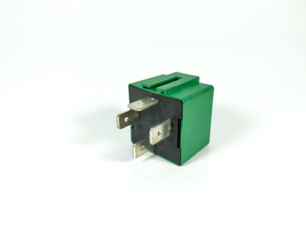
Relays are relatively simple, and there’s a standard 5 or 4-prong relay that almost everyone uses. The 5th prong (87b or 87a) is not usually used unless for particular circumstances. 

On a standard relay, there’s a switch system working at a lower amperage than what the component uses.

A relay protects a switch circuit since most automotive sockets aren’t designed to convey high currents. The relays consume the current turned on by a triggered connection either by a temperature transmitter or switch.

Hence, why are two wires of a bigger gauge size compared to the other two?

To turn on the relay, the 2 smaller wires create a connection from ground to hot; over 12 V are received from the ignition source, and a negative connection is received from the temperature transmitter designed to turn on at 1850C.

Once the connection is created, a magnetic pull completes the connection between 30 and 87 terminals, totally isolated from the switch connection.

Despite it not being crucial to connect the 30 to your battery (12 V power source), it’s the standard. That connection provides the 12 V to the component (fan) connected to terminal 87. 

Relays are capable of handling loads of higher current compared to switches. However, even relays have current rating capacity they can’t exceed.

If exposed to an excessively high current, the circuit will open, and the relay won’t work. Therefore, it’s essential to use a relay with the current load rating that your fans need.

Fan Relay

Caption: Fan Relay

When Do You Need a Second Fan Relay Kit?

With a smaller fan, you can connect both fans to one relay and install a fuse to protect your circuit while still providing sufficient current flow without going over the fuse rating. If your fuse blows, this is a sign that you’re drawing too much power on your system and need to add a second relay kit.

If you have a bigger fan that draws over 15 amps, it’s best to install a second relay kit.

Will a Custom Relay Wiring Harness Make Installation Easy?

If you buy a relay kit, it contains all the necessary connectors to splice wires together. It’s highly recommended to use a good crimp connector and follow the instructions provided in order to ensure you have a hassle-free installation.

However, you can make the installation way easier by customizing your own relay wiring harness.

For instance, an immaculately configured relay wiring harness has fuses in the power supply side of the headlamp power circuit, very close to the power pickup point, inches away from the alternator B+ terminal or battery positive terminal. 

Conclusion

As you can see, an electric fan relay is necessary to ensure the painless performance of your engine cooling system.

Additionally, you can also add an air conditioning relay.

It allows extra automation from the ac pressure switch for additional temperature readings. 

Consult Cloom for all your automobile wiring harness solutions and installation guides.

How to Wire a Starter Solenoid: Automobile Guides

Car starter solenoid

Are your mechanic bills spiraling out of control?

Chances are you are paying for a repair job you could do yourself.

Unfortunately, many modern vehicle owners lack the basic knowledge of how a car functions.

For example, do you know where your car’s starter solenoid is?

Or Are you aware of how to wire a starter solenoid?

If the above questions sound Martian, buckle up and continue reading.

Below is Cloom’s DIY guide on the starting system.

With this information in mind, you can replace the starter solenoid or relay it yourself.

What is A Starting System?

Diagram showing a car starter system

Diagram showing a car starter system

Although technology has changed much of what is in a car, the ignition components are still more or less the same.

Battery Cables

Car battery cables

Car battery cables

For your engine to start, it needs a high current which usually comes from your car’s battery.

The cables that carry this charge from the battery must be thick enough to withstand the high amount of electricity flowing through them.

When you look at your car battery, you usually see two cables.

These cables connect the battery to your car’s starting system.

First, the red one connects the starter solenoid to its positive terminal.

This wire is usually live, so be careful when handling it.

Then, a black or greenish-yellow cable connects the starter motor to the battery’s negative terminal.

Starter Relay

Car starter relay

Car starter relay

A starter relay controls when the high current flows to the starter motor.

That is, it’s responsible for igniting the starter solenoid so your car can start.

It does so by sending current to the ignition switch.

As such, you can use the battery power for other things, such as using your power windows and car radio without cranking the engine.

The starter relay is thus crucial to the ignition because the high current passing through would fry your car if the relay weren’t there to keep it safe.

Starter Motor

Assorted Car Starter motors

Assorted Car Starter motors

The starter motor is the reason why your car’s engine starts.

It’s usually around where your car’s engine is, but it could also be a separate unit like in BullDozers.

It needs a healthy supply of 12-Volt charge from the battery to perform.

Neutral Safety Switch

neutral safety switch

neutral safety switch

A neutral safety switch prevents your car from jerking when the engine starts.

The neutral safety switch usually works the same in automatic and manual cars, using your car’s PCM inputs to engage.  

Starter solenoid

starter solenoid

starter solenoid

The starter solenoid has two functions in your car’s starting system.

Firstly, it completes the circuit between the starter motor and the power source (car battery).

Then, it engages the starter gear to the engine flywheel facilitating it to crank up.

How does the starting system work?

Start the engine

Start the engine

Moving the ignition to start allows the current to flow to your starter solenoid.

Next, the starter solenoid pushes the motor gear to engage with your engine’s flywheel.

So, the starter motor turns the flywheel that spins the crankshaft, forcing the engine to start.

You should also know that the starting system only works when the car is in Neutral or Park.

Furthermore, the system cuts off once the engine starts revving.

Symptoms that you need a replacement of your starting system

Do you know that most problems are related to the solenoid?

car starting problems

car starting problems

You are missing the distinct click noise when starting the engine.

Most cars produce a clicking sound right before an engine starts.

It results from the starter relay switch completing the circuit and the starter solenoid engaging the starter motor with your engine’s flywheel.

So, failure to hear this sound when powering your car indicates a problem with one of the two.

You experience a continuous clicking noise when starting your engine.

Any rapid noises from your vehicle or show that something is wrong.

For example, if your car keeps clicking rapidly with each start, you have solenoid problems.

In most cases, such noises mean the power received is not enough to start your motor.

So, before you rush to replace your solenoid, check your battery and alternator first.

Your engine has a noticeably slow crank.

Engine cranking is a fast motion that only takes a few seconds.

Yet, sometimes your car sounds like it is struggling to get going.

Some instances may result from a low battery.

But, if the issue persists after jumping the power source, the chances are that you have a solenoid with burnt contacts.

Thus, your only way out is to replace it with a new one.

No crank of the engine.

Finally, you know you must replace your solenoid when your engine doesn’t start.

For example, as you turn the ignition key, all car functions are fine, but the starter motor won’t engage no matter what you do.

The first opinion is to check for poor connections.

If everything is fine, then your best bet is to replace the starter solenoid, which is likely why your car won’t start.

The Importance of a Starter Solenoid

A solenoid is a vital part of your car’s starting system. The solenoid efficiently engages your starter motor, protects the motor from damage, ensures safety, and assists in prolonging the life of your car’s electrical system.

If you’re experiencing any issues with the solenoid, it’s important to have a professional electrician or mechanic take a look.

Starter Solenoid

Caption: Starter Solenoid

Symptoms of a Failing Starter Solenoid

The symptoms of a faulty starter solenoid could overlap with the symptoms of a faulty starter; however, the opposite doesn’t apply. Therefore, any whining noise, clicking, and cranking but failing to start aren’t symptoms of a faulty solenoid, just your starter.

The primary symptom of a faulty starter solenoid is the absence of a response from your engine once you turn your ignition key.

The best method of testing a solenoid is by attempting the shorting method or checking the voltage using a multimeter across the large poles with and without turning the ignition key. If no current is detected, this is a clear sign that the mechanism of the solenoid is faulty.

Multimeter

Caption: Multimeter

How to Replace a Starter Solenoid

The process of replacing a starter solenoid is not so difficult. All you need is a socket set or a couple of wrenches and, in some cases, a wire brush for cleaning wires. Simply follow the steps below.

  1. Find your starter solenoid, usually mounted in your starter or on the side of your engine bay.
  2. Keep track of the mounting positions for your wires and make marks if necessary.
  3. Disconnect the ignition wire and unscrew any bolts, keeping the power lines in position.
  4. Unscrew the solenoid mounting bolts.
  5. Install your new solenoid and reconnect the wires.
  6. Try starting your engine to ensure everything works.

Then, How do you Wire a Starter Solenoid?

Starter solenoids come in two types.

Firstly, you can use the on-starter solenoid that directly mounts on your car’s starter motor. 

Or, you can also opt for a remote-mounted solenoid.

These types of solenoids operate across a wide temperature range and are pilot-operated.

Additionally, they feature a single coil spring return and come with SIL 2 & 3 certification.

Furthermore, they can either feature a 3-pole or 4-pole solenoid switch.

The procedure is different when you use either pole.

On-Starter Solenoid vs. Remote-Mounted Solenoid

on-starter solenoid

on-starter solenoid

  1. First, secure your vehicle using chokes on the front and back tires. Then, disconnect your car’s negative battery terminal.
  2. Secondly, lift your car using the stock jar to a height with enough space to get underneath. Additionally, add a jack stand near the jacking point for extra security.
  3. Then, crawl underneath and mark each wire referencing their respective connection locations. You can use masking tape and a marker for the labeling. Additionally, use a wrench to disconnect each wire and unplug the wiring harness from the solenoid.
  4. Subsequently, remove the starter motor carefully by unbolting it from your engine. You will need to unbolt remote-mounted solenoids for their specific installation area.
  5. Finally, reconnect the wires to the new solenoid as per the labels. Then, lower your car from the jack and reconnect your battery’s negative terminal.

3-pole starter solenoid vs. 4-pole starter solenoid

4-pole starter solenoid

4-pole starter solenoid

The main difference between a 3-pole starter solenoid and a 4-point starter solenoid is how they work and their connection to the field coil.

In 4-pole starter solenoids, the four terminals speed up the motor.

On the other hand, in 3-pole solenoids, the terminals’ primary function is to launch the starter motor.

Furthermore, 3-pole solenoids feature a series connection with the field coil compared to the parallel one in 4-pole solenoids.

Thus, 4-pole solenoids can still function with varying battery charges since the NVC and field winding are on different circuits.

However, the connection process is generally the same. If you position it on your bumper or another part of your engine bay, then the solenoid’s backplate acts as a ground; therefore, you won’t need any grounding wire.

Four Pole Solenoid

You can easily identify the 4 pole solenoid thanks to the two front-facing poles and the other two poles protruding to the right and left. 

The left pole functions as an input connecting to your battery cable. On the other hand, the right pole functions as an output towards your starter. The two poles are distinguishable by thickness and ability to facilitate heavy gauge wires transporting high currents.

On the front side of your solenoid, there are two poles opposite each other. The thinner wire travels from your starter switch through your neutral safety switch (and, in some cases, relay) down to your left pole. Therefore, acting as a control for the relay while your starter and battery poles transfer power.

Three Pole Solenoid

The 3-pole solenoid connects similarly to the 4-pole solenoid. However, they do not have a smaller terminal for the ballast resistor or ignition coil connection.

Depending on the pole’s orientation, it could be difficult to determine the purpose of the poles.

Some designs have the poles sticking out right, left, and up of the solenoid, meaning none of the poles face forward.

The slim pole should face up and connect to the starter switch. While the right pole connects to the starter and the left connects to the battery.

Some designs have all the poles facing forward; however, the same rule applies with the starter pole always at the top, splitting the right and left poles.

To play it safe, it’s always best to check the solenoid instructions before jumping to conclusions.

Tips For Troubleshooting Starter Solenoid Wiring Issues

If you are having some problems with the starter wiring, here are some tips to help you resolve the issue.

  • Check your battery – first, check your battery to ensure it’s fully charged and has at least 2.6 V. If your battery’s dead or low on charge, it could be the root of your problems.
  • Inspect your wiring – inspect the cables from your starter to your battery for any signs of damage like frayed cords or corrosion. If there are any issues, replace or repair them accordingly.
  • Check your solenoid connections – check the connections at your starter to ensure they’re secure and tight. A loose connection could cause the solenoid to experience some issues.
  • Test your solenoid – test your solenoid for voltage and continuity using a multimeter. If there’s no voltage or continuity, you might need to replace your solenoid.
  • Check your starter – if no red flags appear on the solenoid test, you’ll need to check the starter itself. Ensure your starter is properly connected and all the wires are in good condition. If you find the starter defective, you’ll need to replace it.
  • Check your ignition switch – if both the solenoid and starter are properly functioning, the problem could be the ignition switch.

Conclusion

Starter solenoids and starter relays are essential parts of any vehicle’s ignition system.

They need regular maintenance checks and wiring to continue working properly.

But no matter what kind of help you need, Cloom is always available to provide you with the best automobile wire harness solutions and guides to ensure your vehicle is always running. 

How To Tell What Gauge Wire Is: Learn Different Methods to Calculate It

How To Tell What Gauge Wire Is

The gauge of the wire tells how much electrical current a wire can carry without heating up.

Suppose you accidentally pass a current higher than a particular wire gauge’s rated current carrying capacity.

The electrical wiring may heat up and generate heat leading to wire deterioration. It may further affect its insulation which may cause an electrical fire.

Then, how to tell what gauge wire is?

There are two ways. Let’s get into the details of both methods.

Gauging Round Solid Wire With a Wire Stripper:

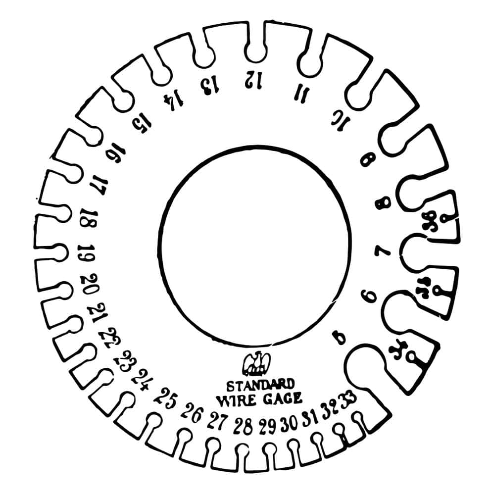
Get yourself a wire gauging tool. 

Wire gauging tools are basically a piece of metal (usually rectangular or circular) studded with numerous holes around its perimeter. Each hole has a label that corresponds to a certain gauge size. 

  • You can buy a wire gauging tool at a home supply store or local hardware store.
  • Ensure your gauge tool specifies the measurement system it corresponds with. If you’re in North America, your gauging tool will probably measure according to the AWG scale.

The next step is estimating the gauge size of your wire. 

Estimate the approximate size of your wire and try to determine the gauge holes that are the same size. Doing so will save you time because you’ll avoid the hassle of having to fit your wire into excessively large or small holes on the scale. 

Illustration of Wire Gauging Tool

Caption: Illustration of Wire Gauging Tool

Now, slide the wire into the approximate gauges and see where it fits. 

Put the wire into every approximate gauge until you find the perfect gauge. The wire corresponds to the smallest gauge it can fit into. The fit should be tight but not excessively snug.

  • Keep in mind every gauge will have a slightly larger gauge next to it. Don’t use such holes to measure the gauge size. Such gauges are there in order to enable you to easily remove the wire from the hole.

It’s best to compare your wire to another wire that you know the gauge. 

If you don’t have access to a wire gauging tool, you can attempt to determine the gauge of your wire by comparing it to another with a predetermined gauge size. For instance, if you have a wire with a small diameter, you can compare it to a wire of gauge 22, 21, and 20 to see which is closest.

  • If you don’t have any wires with a predetermined gauge size, you can always go to a local hardware store for further assistance. If they don’t have a wire gauging tool, they will probably have a variety of wires with a predetermined gauge that you can use to compare your wire with.
wire strippers

Caption: wire strippers

Gauging Stranded Wire By Measuring Cross-section

How To Tell What Gauge Wire Is: Measure the diameter of a single wire. 

A stranded wire consists of numerous thin wires twisted together to form a single wire. In order to calculate the gauge of a stranded wire, you’ll need to determine the diameter of a single wire strand in inches or multimeters.

  • If your wire has a very small diameter (very large gauge) and you can’t measure it using a ruler, use a wire and conduit measuring device. You can get this tool at most hardware stores.

Next, multiply the diameter of your wire by itself. 

If the diameter of your wire was 0.0005 inches, multiply the value by itself. You’ll need to count the individual strands and then multiply the stranded wire diameter by the number of strands. For instance, if your wire has 20 strands, multiply the value by 0.0005.

  • The result will give you the CMA (Circular Mils) value for your stranded wire. This is another popularly used wire gauge scale that calculates the circular area of a wire. 
  • As a general rule, smaller diameter wires (large gauge) contain fewer strands. Wires with a smaller diameter may have seven or eight strands. On the other hand, larger diameter wires (smaller gauge) might have as much as 30. 40 or 100 strands.

Determine your wire’s corresponding AWG size. 

Once you determine the CMA of your stranded wire, check online to determine the corresponding AWG size. Also, you could simply visit a local hardware store that often has a hardcopy gauge comparison table.

  • For instance, if the diameter of your wire strand is 0.005 inches and your stranded wire has 20 strands, then the corresponding CMA will be 525 with a 22 AWG. 

How To Tell What Gauge Wire Is: Wire Gauge Reference Table (AWG)

AWGDiameter (MM)Diameter (Inches)SWGBWGCircular Mils
36 AWG0.127000.005000393524.999282
34 AWG0.160020.006300373439.688860
32 AWG0.203200.008000353363.998162
30 AWG0.254000.010000333199.997128
28 AWG0.320040.0126003029158.755440
26 AWG0.403860.0159002727252.802739
24 AWG0.510540.0201002525403.998397
22 AWG0.642620.0253002323640.071617
20 AWG0.812800.03200021211023.970591
18 AWG1.023620.04030019201624.043356
16 AWG1.290320.05080018182580.565884
14 AWG1.628140.06410016164108.691995
12 AWG2.052320.080800141410383.311783
10 AWG2.588260.101900121216511.775768
8 AWG3.263900.128500101026250.698587
6 AWG4.115380.1620237841614.804788
4 AWG5.181600.2040005666562.088282
2 AWG6.553200.258000231333075.217970
2/0 AWG9.265920.3648002/02/0167767.341584
3/0 AWG10.403840.4096003/03/0211593.922848
4/0 AWG11.684000.4600004/04/0211593.922848
5/0 AWG13.119100.5165007/0266764.588301
6/0 AWG14.732000.580000336390.338592
  • SWG – refers to the Sterling or Standard Wire gauge
  • BWG –  refers to the British Wire Gauge (old British system used in the past)
voltage tester

Caption: voltage tester

Conclusion:

Determining wire gauges requires minimal equipment, which works virtually for all wires and cables.

The cables are the main functional component of any electrical device.

Always look for high quality and the right gauge.

Cloom is the world’s leading manufacturer of top-quality wiring harnesses and customized cable assemblies, which you get after the toughest quality assurance tests.

Ethernet Cable Colors: How Much Do They Matter?

Blue ethernet cables

Buying an ethernet cable is not as easy as it seems. It has many varieties based on its types, lengths, and colors.

This article will discuss ethernet cable colors and what matters while picking an ethernet cable.

Understanding Ethernet Cable Colors 

Ethernet cables come in different colors, like all other cables.

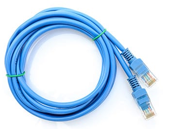
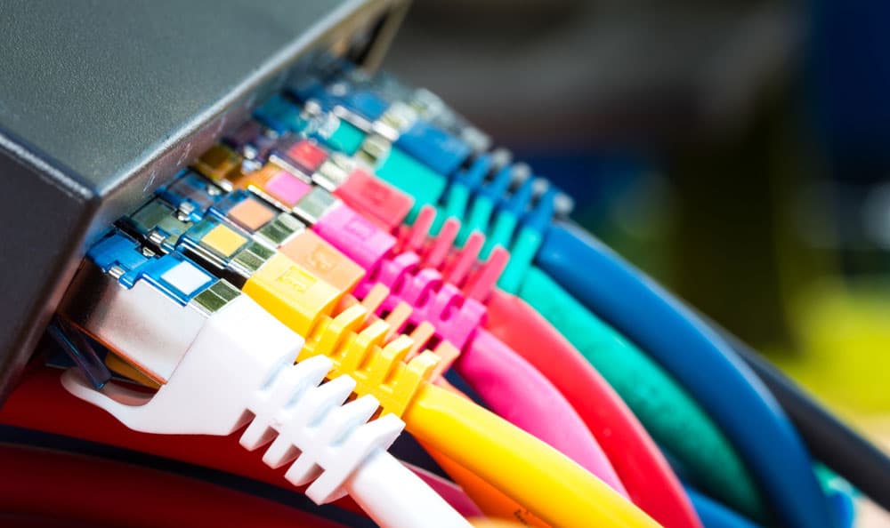
Commonly, you will see gray, yellow, white, orange, and blue colors in them.

One color is not better than the other, but the colors help you to identify the cable for its intended application. 

Let’s understand this with an example. In the Department of Defense, the government uses several colors for all the ethernet cables to classify them based on data transmitted through that cable.

Red cable for mid-level, blue cable for unclassified data, and yellow cable for some confidential data.

Colors help in cable management. Imagine that you have a business where you have a server or a server room.

It may have a particular color scheme, and organizing your cables according to that color scheme will make your network infrastructure more efficient.

In addition, the differently colored cables make identifying and troubleshooting problems easy.

LAN network ethernet cable. 

LAN network ethernet cable. 

Why Do Ethernet Cables Come In Different Colors?

The cable’s functions have nothing to do with its color. Often, specific colors are used to identify connection types and intended applications or to differentiate cables from different manufacturers, helping with cable management.

Another reason why ethernet cables are available in different colors is to indicate the different performance levels or categories.

Some of the various ethernet categories include Cat 5, Cat 6, and Cat 7 with each possessing different performance capabilities.

The different color cables make it simpler for installers and technicians to use the capabilities of a specific cable.

Furthermore, different colors could indicate the intended use of a cable. For instance, certain cables are designed especially for outdoor use; hence, the different colors indicate their water resistance and durability.

Other ethernet cables are designed for industrial applications, and their different color indicates their resistance to extreme temperatures and chemicals.

Also, different colors are used to identify cable lengths. For instance, a red ethernet cable could indicate the cable is 5 meters, while a blue cable indicates 10 meters.

This makes it easier for installers and technicians to determine the right cable for the job.

Ethernet Cable Outer Jacket’s Colors vs Twisted Internal Wires Colors

The colors of Cat 6a, Cat 6, Cat 5e, and Cat 5 ethernet cables indicate a specific system or application, like equipment connections or network connectivity. However, you should not confuse this for the color coding of the internal twisted wires in each cable.

Different Color Ethernet Cables

Caption: Different Color Ethernet Cables

Outer Jacket’s Color Coding of Ethernet Cables

Common Ethernet Color Coding Assignments

Although there’s no industry standard, here’s an example of color coding assignments businesses may use;

  • Yellow – Camera
  • Red – Emergency systems / Phones
  • White – Security
  • Blue – Network Connectivity
  • Black – Workstation / Equipment
  • Grey – Jumpers / Interconnects

Also, color management could be used to differentiate various networks or security levels, such as test LANs, management LANs, production LANs, and DMZs.

Since some vendors or companies have their preferred labeling, it’s best to identify the colors and applications from a currently available schematic.

Ethernet Cable Color Coding By Year 

You can use a cable’s color to determine when the cable was installed. Some vendors determine the year work was done by choosing a certain color.

Therefore, making it easier for technicians and customers to easily determine the age of the cables and when they were installed. Here’s an example of cable color coding by year of installation.

  • Yellow – 2019
  • Blue – 2018
  • Purple – 2017

Twisted Internal Wire’s Color Coding of Ethernet Cables

Almost every category, from Cat 5 to Cat 6 and Cat 8, uses an RJ45 connector, which is different depending on the arrangement of wires into the connector.

There are two variations of RJ45 connectors: T568A and T568B. These serve as pins in and out for cables that facilitate data transfer.

However, the key difference between the two is the wiring in green and orange pairs.

 RJ45 Connector

Caption: RJ45 Connector

RJ45 Cable Pinout Color Code T568A

T569A is one of the most popularly used pin-out configurations with ethernet cables. One of its primary features is compatibility with double-pair and single-pair standards, commonly known as USOC

PinColorSignal DescriptionSignal Type
1Green/WhiteTransmit +TX1+
2GreenTransmit –TX1-
3Orange/WhiteReceive +RX+
4BlueBi-Directional Transmit +TX2+
5Blue/WhiteBi-Directional Transmit –TX2-
6OrangeReceive – RX-
7Brown/WhiteBi-Directional Transmit +TX3+
8BrownBi-Directional Transmit –TX3-

RJ45 Cable Pinout Color Code T568B

More commonly used compared to the T568A standard in ethernet cables, T568B has better noise blocking. It does signal separation better than T568A. However, it provides only one USOC wiring arrangement and supports just reverse compatibility.

PinColorSignal DescriptionSignal types
1Orange/WhiteBi-Directional Transmit+TX1+
2OrangeBi-Directional Transmit-TX1-
3Green/WhiteReceive +RX+
4BlueBi-Directional Transmit+TX2+
5Blue/WhiteBi-Directional Transmit-TX2-
6GreenReceive-RX-
7Brown/WhiteBi-Directional Transmit+TX3+
8BrownBi-Directional Transmit-TX3-
Colored ethernet cables

Colored ethernet cables

Do Ethernet cable colors matter?

There is no relation between ethernet cable color to its performance.

Cable vendors only give specific colors to the ethernet cables to understand their use and connection type and differentiate their connections from their competitors.

Colorful network cables 

Then what matters?

Since colors do not enhance performance, you should consider other characteristics that matter when looking for one.

Ethernet cable Cat

Here we will describe the performance and use of each cable type except cat3 and cat5, as they are slow and discontinued.

Cat5 and Cat5e: Here, the “e” indicates enhanced features.

You compare cat5 and cat5e; you will find no physical differences.

The only difference is that manufacturers have followed more stringent testing standards to eliminate crosstalk (unwanted transferring of signals between communication channels). 

Cat 5e Ethernet cables are the most used as they have low production costs and support high-speed signal transfer.

Cat6 And Cat6a:

Cat6 cables support higher bandwidths than cat 5 and 5e, so they come at a higher price.

So, you can choose foil or braided shields to protect the twisted wires inside the cable.  

In Cat 6a cable, the letter “a” stands for augmented.

These cables are one step better than Cat 6 cables, and support bandwidth doubles that of Cat 6 cables.

So, you can get high transmission speeds over long lengths.

Cat 6a cables have shields and sheathing that are thick enough to eliminate crosstalk. 

Cat 7 and Cat 7a: These cables support higher bandwidth (100Gbps at a range of 15 meters) and faster signal transmission.

Additionally, these shielded cables use a GigaGate45 connector that shows backward compatibility with RJ45 Ethernet ports.

Although the GigaGate45 connector is a proprietary component with backward compatibility, manufacturers still faced issues with the Cat 7 cable’s previous standards.

As a result, they avoid it and use cat 6a instead.

Similar to Cat 7, Cat 7a also has high specifications. It supports 40-gigabit ethernet connections up to 50 meters with some improvement.

However, it only supports a few networks and is expensive, so you must prefer it only in some exceptional cases.

Cat 8: These ethernet cables have the highest specifications as they support a max frequency of 2,000 MHz with a speed of 40Gbps at 30m.

As these cables are always shielded to support such high frequency. 

t 8 ethernet cables support two connectors; thus, you can only connect three cables with a total length of 30 meters. 

High specifications make them overkill for regular residential use.

So, the cable meets the newest IEEE standards, which makes it a good choice for future-proofing despite its high cost. 

Caption: Cat and performance

Ethernet connectors

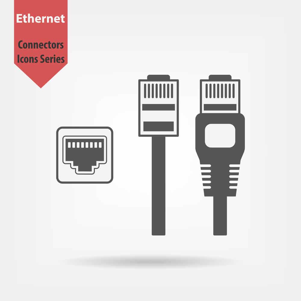
Ethernet cables use special ethernet connectors with a unique design, as these connectors have eight pins that keep the cable locked into place.

Typically, you can call them an 8P8C connector.

However, there are several 8P8C connectors with differences, which put the ethernet cables into different categories.

RJ45:

RJ45 stands for Registered Jack 45, the standard form that almost all ethernet cables (Cat1-Cat 6 and Cat 8) use.

Based on the wires’ color and arrangement, you will find two variations in them.

Is the T568B standard (more common and popular) and the T568A standard (less common and less important)?

GG45: as mentioned before, these are specific connectors for Cat 7 cables, and these connectors have some additional connectors to give versatility in frequency.

T ough it has backward compatibility with the RJ45 connector, this new connector seemed unimportant, and thus Cat 8 cables resumed RJ45 connectors.

Ether CON RJ45: RJ45 connectors are very easy to use, but there is doubt about their durability as they have built-in plastic chips which break easily.

As a result, manufacturers developed a rugged version of RJ45 connectors.

You can use them in professional Audio/Video applications that need long-term durability.

Ethernet Cable shields

Based on the outer shielding, twisted wires in the Ethernet cables are divided into the following categories.

Unshielded twisted pairs or UTP: You will find no foil or intertwined protective cover in these twisted pairs.

These designs make the cable flexible and highly inexpensive.

However, UTP cables may not have excellent signal quality, and you may experience crosstalk.

Shielded twisted pair or STP: These ethernet cables have a robust, braided shield T is a shield comprising copper or any other conductive material.

As an s result of this shield, these cables deliver good signal quality with reduced noise.

Foiled Twisted pairs or FTP/SFTP: You will find a foil shield that covers the twisted wires inside these cables to boost connectivity, reduce noise and enhance signal strength.

Ethernet cable compatibility

The best part about ethernet cables is that you can interchange them.

However, you may face issues with old cables like Cat 5 related to the fast data transfer speed. 

You can easily insert a cat 5 cable into a router with the newest 10G Ethernet interface, but the cable will slow the data transfer speed.

You can also plug a Cat 7 cable into a long-standing router that does not support high speeds, but it will work fine.

Ethernet Cable length

The standard measurements are 0.5, 1, 1.5, 2, 5, 10, and 20 meters Y; you can get these cable lengths from almost every supplier.

If you want long ethernet cables, measurements up to 75 meters are available but are more expensive.

You can get a big ethernet cable reel if you want cables for a house or any other permanent wiring.

There are reeled up to 500 meters or more. 
Ethernet cable jacket rating

Depending on the location, different types of cable jackets are based on the material. 

CM-rated cables: Have ethernet cables run from your personal or office computers to the wall port?

These are CM-rated cables commonly known as patch cords.

These cables are available in a stranded form; thus, they are very flexible, so you can connect short runs to your PCs to server racks.

CMR-rated cables: In these CM-rated cables, R stands for the riser M only; these cables are used as riser cables rather than patch cables, i.e., these cables run through the top or bottom of the walls or basement to the upper floor. 

You can also use CMR cables for residential applications.

They have to undergo a burn test to prove their self-extinguishing nature, but these cables are less strict regarding fire requirements than CMP cables.

But they are more flexible, so if you use them at home for networking, it would be easier to arrange them.

CMP-rated cables: Here, the P stands for the plenum M style; you will find these cables in homes and offices if networking is done through ducts.

Ethernet connectors and socket 

Ethernet connectors and socket 

Conclusion

The color code of the outer plastic jacket in the Ethernet cable does not indicate anything.

However, engineers sometimes use colored cables in different zones in local area networks to understand each cable’s purpose.

Tough color does not matter; quality does.

If you want high-quality ethernet cables for your home or office networking, contact Cloom.

Continuity Test: A Complete Guide of Its “What” And “How-to-do”

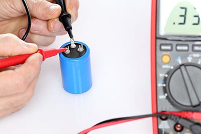
Electrician testing a capacitor with a multimeter

Do you know what the basis of an electric device is?

It’s the circuit. The circuit is a circular path having the same beginning and ending points.

The current flows in a circuit from a power source and takes it to the electrical device.

This current comes back to the power source.

And here’s how the circuit completes itself.

The device works well until and unless there is a perfect continuity test of the current.

If continuity breaks, the device stops working.

It’s quite easy to check the continuity with the continuity test.

Now, let’s know what and how about this test in detail.

What is a continuity test?

As the name suggests, the continuity test checks the continuity of the current.

Simply put, it checks if the current flows freely from one end to the other.

There are devices such as multimeters or ohmmeters to perform this test.

You can also find some specialized continuity testers for the test.

These testers are basic, low-cost, and have a bulb to indicate the current flow. 

In this test, you provide a small voltage between the two testing points of the circuit.

If something interrupts the current flow (or electrons), the circuit is open.

The interruptions can be due to damaged components, cracked conductors, or high resistance.

If there are no interruptions, it is a continuous circuit.

Why do you conduct a continuity test?

In electronics, continuity testing is quite important.

You can perform this test to check various things within a circuit, such as:

  • You can check the quality of soldering. Sometimes, soldering is a cold solder connection. Most of the time, you cannot identify it visually. Such soldering appears connected, but in reality, they are not.
  • Sometimes, there are broken wires within the circuit. You can check the wire connection with the continuity test. This is especially important for power cords and headphone wires. These wires appear normal from the outside, but there can be some damage in reality.
  • Also, identify any damaged components within the circuit.
  • Do this test to know if two points have a connection in them or not, as in PCB.
  • You can also verify the schematic diagram with the continuity test.
Electric multimeter

Image: Electric multimeter

How to test continuity with a multimeter:

As discussed above, you can use a multimeter to perform this test. To learn more about these safety tools, read further.

First, understand the Multimeter or Ohmmeter.

This device can test various other electrical issues apart from testing the continuity of the electrical path.

You can test for AC/DC voltage, open circuit, short circuit, or amperage.

This is a rectangular tool with a dial or digital setting. With this dial, you can set the tool for the test you want to perform.

Like a continuity tester, a multimeter also powers through a battery.

You will find multiple holes at the front of the multimeter. Out of these, one is “COM,” which means short for “common.” This is for the ground. Another hole is mAVΩ, which means “measure amperage, voltage ohms. This is used to measure current. Apart from these two, there is a port of “10A”. You can use this for measuring very high currents. 

It has two wire leads: red and black. You have to plug the black into the COM slot and the red into the mAVΩ slot of the multimeter. The other ends of the wires have metal probes.

Continuity Test for capacitor:

Before performing the test, you must remove the capacitor from the circuit and discharge it completely.

Test with continuity mode:

  • First of all, set the dial to continuity mode.
  • Secondly, plugin red and black probes into multimeter sockets as described above.
  • Connect the other end of the multimeter’s red probe to the capacitor’s positive terminal.
  • Following this, connect the capacitor’s negative terminal with the multimeter’s black probe.
  • If the capacitor works well, the multimeter will show”0” initially. The multimeter charges the capacitor. With this, the reading reaches infinity or OL. The “OL” reading shows that the capacitor is open and charged completely.
  • You will see a very low value (short) or infinity (open) in a damaged capacitor
continuity test for an extension cable

Image: continuity test for an extension cable

Test with resistance mode:

  • First, set the multimeter to resistance mode.
  • Connect the red and black probes to the positive and negative terminals of the capacitor.
  • The capacitor is good if the resistance readings start from “0” and reach infinity. This shows that it was charging initially.
  • If you get a very high initial resistance, it means the capacitor is damaged.
  • If there is low resistance, your capacitor is short.

Continuity Test for Inductors:

An inductor is a coil; to test it, you must remove it from the circuit.

Test with continuity mode: 

As described above, set the dial to continuity mode.

Plug red and black probes into multimeter COM and V-ohm sockets

Connect the red and black probes to the positive and negative terminals.

In case the inductor is working well, the multimeter will beep. You will see a very low value of readings. However, you cannot identify any short turns of the inductor.

In case of a damaged inductor, the multimeter will not beep and show “1” or “OL” readings indicating an open circuit.

Test with resistance mode: 

First, set the multimeter to resistance mode. Try to adjust it to the lowest possible readings.

Secondly, connect the red and black probes to the positive and negative terminals of the inductor.

If the ohmmeter shows a few ohms resistance, the inductor is good. 

And if you get very high initial resistance, the inductor is damaged.

Or if there is low resistance (near zero), the inductor might have short turns.

How To Test a Wire For Continuity With a Multimeter?

Testing For Continuity Using a Multimeter

Caption: Testing For Continuity Using a Multimeter

  • The first step is connecting the red and black terminals with the respective slots. 
  • Then, once you turn on the multimeter, set the dial on the device to test for continuity. However, if your device doesn’t seem to have a continuity setting, you may still do the test by setting the dial to the smallest amount in resistance mode.
  • Now, make sure the device is working by touching the terminal’s metal parts together. Keep in mind:
  1. If the value you get on your multimeter is lower than one, then the device is properly functioning. 
  2. Also, if the value is exactly zero, then the device is functioning. 
  3. However, if the value you get is high or you don’t hear a beep, confirm the dial settings on your device. Next, inspect the ports you plugged into your terminals. 
  4. Replace the terminals before checking the manual to determine how to reset your multimeter. If on the screen it displays one on the far left side and not the position values are normally displayed then it means you have a broken signal. A broken signal is an indication of faulty terminals. 
  5. If the values keep fluctuating a bit, this is perfectly okay. 
  • Turn off and unplug the device you intend on testing. However, it’s obvious that you can not unplug a connected wire. Test the connected wire by turning off the vehicle, appliance, or device.
  • Stick your black terminal on either end of your exposed wire. Ensure that the metal part at the end of your terminal is constantly in contact with the piece you want to test.  
  • Place your red terminal on a different part of your wire while keeping your black terminal on the first end of your current. 
  • Then, press the exposed red terminal on the opposite end of a linear current, such as the opposite end of your wire.
  • Give the values some time to stabilize, then confirm the readings to determine the resistance. Note:
  1. If the reading is zero, this indicates perfect continuity.
  2. If the reading is lower, this indicates bad terminals or good continuity.
  3. If the reading is between 1 – 10, whether this is a problem depends on the device. Therefore, refer to the device’s manual to determine if this is an acceptable level of resistance. In the meantime you could play it safe and postpone using the device.
  4. If the reading is over 10, this indicates poor continuity. This means the resistance is higher than normal, and you should replace the wire.
  5. If you get no reading, this indicates that you have a broken circuit.
Electrician checking fuse box

Image: Electrician checking the fuse box

Continuity Test for fuse:

Repeat the same process as you did with cables and wires.

The meter reading “zero” means the fuse is in good condition.

While an “infinite” reading means fuse continuity is broken.

Continuity Test for switch/push buttons:

You can conduct the same test as above for switches and push buttons.

However, in this case, you need to do the test in both “on” and “off” conditions.

Firstly, take the reading in the “ON” mode. Secondly, repeat the process for the “OFF” mode.

In the first test, you must get “zero” and “infinite” for the second test.

This means your switch and push-button are in good condition.

On the other hand, if both readings are “0” or “infinite,” the switch is in a short circuit.

In this case, you must replace the switch/push button.

How to Test Continuity without A Multimeter:

You can use a Continuity Tester for testing metal pathways.

A battery is the source of power for this tester. You will find a metal probe at one end of this tool. On the other end, there is a wire lead, which either has an alligator clip or a probe. 

Its working is quite simple. Just touch the metal probe and wire lead with each other.

If the circuit is complete, the light or buzzer will go off. You can also find an LED or any other visual indication in some devices.

Similarly, you can test the electrical path for a device, appliance, or circuit.

Ensure that the power supply is off before using this tester, as using it on live wires is dangerous.

If you do not have one, no worries. You can make a Homemade Continuity Tester.

Get a 9v battery, buzzer or LED resistor, and two wires. Connect them as shown in the figure. Your continuity tester is ready.

Conclusion:

Testing the continuity of circuits is vital for major electronics repair.

Checking the circuit continuity helps you pinpoint any issues with the integrity of the circuit.

However, to prevent any issues with your electrical devices, you must start early.

Go for high-quality cable assemblies and wiring harnesses.

Cloom offers you the best solution for wire assemblies.

We also have the custom designing option with us.

SDI Cable: All You Need to Know How to Choose the Cable You Need

SDI Cable

What is it that you need to look for in an SDI cable? Should you go for an HDMI connector or an SDI one?

We look at the SDI interface, the different types of SDI cables, and how these can be a better choice in many instances.

Do cables such as SDI or HDMI confuse you? Don’t worry. This article will help you pass through the turbulent waters of cable.

Video SDI cables

Chapter 1: What is SDI Cable?

Now, what is SDI? SDI stands for serial digital interface or SDI cable for short. It is a standard used for transmitting digital video over long distances.

It is the most common cable found; all the broadcasters prefer SDI and use it.

The cable that connects your TV set-top boxes or TVs is probably an SDI cable. SDI cable belongs to the family of digital video interfaces.

The Society of Motion Picture and Television Engineers [SMPTE] named it in 1989. Compared to HDMI, display port, DVI, or VGA connector, it is pretty old.

You can think of SDI Cable as a grandfather, while the others as grandchildren.

SDI cable was first standardized in 1989, but it’s 2019 now. SDI cable has gone through many upgrades over the decades.

The enhancements are mostly done to increase signal quality and transmit more data.

About SDI Cable

Whether watching a live show or regular television, SDI cable brings you that feed. The reason for the SDI cables preference over other cables is:

  • Transmission of audio and video over the long-range [300ft]. Amplifiers and repeaters increase this range even further.
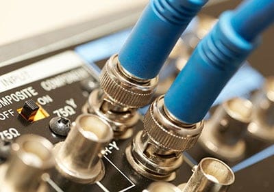
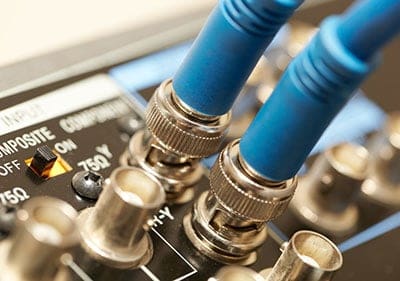
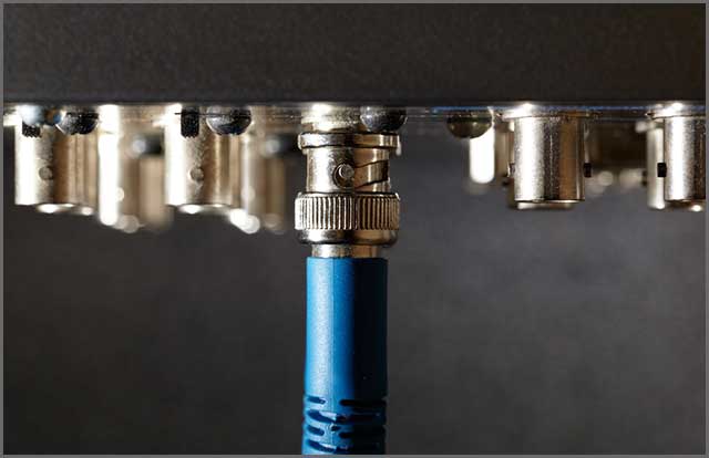
  • Has a BNC connector which has a lock-in mechanism.
  • Cheaper compared to other cables as it is mass-produced.
  • It’s reliable, robust, and sturdy.
  • Works wonders while sending uncompressed audio and video signals.
SDI Cable Macro slot

Types of SDI Standard

Now, there are various standards of SDI cable. Here is a look.

  • SD-SDI, with a bit rate of 270Mbit/s, was introduced in 1989. It can transmit a video format of 480i and 576i.
  • HD-SDI, with a bit rate of 1.485Gbit/s, was introduced in 1998. It can transmit a video format of 720P/1080i.
  • 3G-SDI with a bit rate of 2.970Gbit/s introduced in 2006. It can transfer a video format of 1080P 60F/s.
  • 6G-SDI with a bit rate of 6Gbit/s introduced in 2015. It can transmit a video format of 4K 30F/s.
  • 12G-SDI with a bit rate of 12Gbit/s introduced in 2015. It can transfer a video format of 4K 60F/s.
  • 24G-SDI is already in development, with a bit rate of 24Gbit/s.

Video Payload and Blanking

Now time for some technical stuff. Do you know how data goes through?

Here is a simple rundown. The data go in packets called payloads.

At the same time, the information about the destination is in the header.

Video payloads in the earlier versions of SDI were a far cry compared to the new ones.

The higher the video payload, the higher will be the video definition.

Have you ever wondered how the secondary data, such as subtitles, stock files, etc., come into your live feed?

This answer is blank. Blanking is the interval between the end of the last line of the frame to the first line of the next frame. 

There are three types of blanking – Horizontal, Vertical, and Field.

Blanking is used earlier for better video quality during CRT TVs.

Nowadays, it’s more to carry secondary data and audio-video synchronization.

SDI cable uses a real-time transport protocol [RTP].

It helps in the real-time transmission of data on multiple channels.

That also helps in better payload and hence, better video quality.  

Chapter 2: SDI Check and SDI Status Display

 SDI checking is important. Some tests are a must for ensuring that SDI is performing satisfactorily. Some of those checks are:

  • SDI check field
  • In-service testing
  • Eye pattern testing
  • Jitter testing

SDI cables go through these checks. It results in the brilliant transmission of audio and video.

SDI status display also gives a summary of several physical layer measurements.

For one, this helps in better configuration. There is an automatic change of the filter settings according to the signal.

During configuring the settings for the transmission, these work wonders.  

Chapter 3: Do You Need SDI Interface – moving from Analog to Digital?

What many people worry about is signal integrity. That is, whether or not your signal will reach its destination without alteration.

I’ll be honest here. No matter what cable you are using, there will be some loss during transmission.

You only need to worry about whether that loss will significantly affect you. If you can’t understand, then let me make it simple.

Let’s start with the basics. All of you know signals in analog or digital carries data.

Analog transmission was the standard in the early 60s, 70s, and before.

Now the digital signal is the undisputed king [no kidding].

The earlier coaxial cable used analog cables.

However, the transmission loss was pretty high. Analog signals transmit data in a waveform.

And when alteration happens, it is progressive and continuous.

In simple words, the more noise, the more the degradation in signal.

Digital signal stores and transmit data in the numeric value of 1& 0.

That is not just easy for transmission but allows less alteration as well.

Due to this, most cable nowadays uses a digital signal, and SDI is no exception.

So, if you want to transmit data, the digital signal is the best.

If you still use analog signals, you should consider moving to digital.

Custom SDI Cables

Chapter 4: Selecting the Proper Manufacturer for SDI Cable Assembly

Looking for the best SDI Cable assembly services?

You can find the SDI port in every major camera. If you’ve ever been to a stadium during a live event, you can see many camerapersons holding cameras.

If you look closely, you can see a lot of black wires. Those are none other than SDI cables.

It may seem a bit crazy. However, here is the thing.

The total length that you see while live streaming is several Kilometers.

It’ll probably burn your pockets if you use HDMI or any other cable – and I am not kidding.

It would help to have a custom SDI Cable manufacturer you could trust.

At CLOOM Tech, you’ve got the right experts to help you.

Have high-bandwidth applications that need a 125 meters transmission distance?

We can help you get the SC-DZ type RG7 cable to help you out. Want to go the economical way?

Try out our choices of RG6 cable.

We can help you design SDI repeaters that can accept two signals together.

Or even convert copper SDI signals into optical SDI format.

That will help for extra-long cable runs of over 300 meters. 

Our cable rating is according to the frequency [Giga Hz].

The higher the Giga Hz, the higher will be the bandwidth. Higher bandwidth equals better video and audio quality.

Many manufacturers make SDI cables, but you need professionals you can trust.

We can custom-assemble SDI cables according to your needs.

Choose from Triax, coax, fiber, or audio cables.

Each comes with its cable and connectors. Talk to us to know more about how we can help.

Chapter 5: HDMI vs. SDI: What’s the Difference?

I am sure many of you want to know the million-dollar question.

What is the difference between HDMI and SDI?

HDMI stands for high-definition multimedia interface. SDI stands for serial digital interface.

Both are for the transmission of audio and video signals.

There are a few differences between them, such as

  • SDI cable uses BNC [British naval connector], whereas HDMI uses the HDMI connector.
  • HDMI uses high bandwidth digital content protection [HDCP] for protection, whereas SDI has no such protection.
  • Speed in HDMI cable is a bit slower due to HDCP than SDI.
  • HDMI cable has 19 pins, whereas SDI cable has only one pin.
  • HDMI cables are more expensive than SDI cables.
  • SDI cables are reliable, and their connectors don’t break easily compared to HDMI cables.
  • HDMI cable is more oriented toward consumers. SDI cable orientation towards professionals.

Chapter 6: SDI Cable vs. Coax

Coaxial cable is the simplest type of cable found. Coaxial cable has a central core, either aluminum or copper, clad in a dielectric constant.

A braided copper mesh surrounds it for shielding, and finally, the insulator over it. 

  • Coaxial cables have a male connector at the ends, which connects to the female connectors. They are the most common use in cable television.
  • SDI is a transmission format. It uses coaxial cables along with BNC [Bayonet Neil Concelman] connector.

The reason for using coaxial cable is that it is very cheap compared to other cables.

All the major institutions, whether the military, bank, or telecom, use SDI.

So, you can think of a coaxial cable as a part of SDI transmission.

Chapter 7: SDI Cable vs. BNC

As you already know about SDI, I will discuss the BNC connector.

BNC connector has a male-mounted connector with a pin connected to the central core.
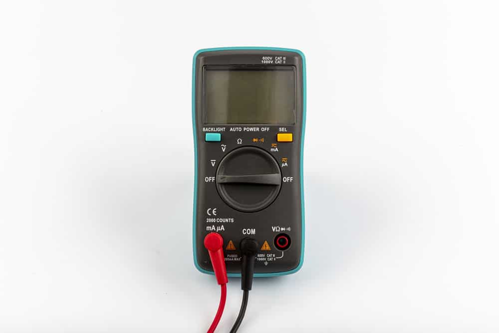
A ring is there with the male member to fasten it to the female member.

This lock-in function is one of the best reasons BNC connectors are sturdier than their peers.

  • You don’t want HDI Connectors Always.

You wouldn’t want wires pulled from the ports whenever someone trips over them.

SDI cable uses a BNC connector, which is very reliable and does not break easily.

HDMI connectors are a pain in the neck precisely because of their fragile nature.
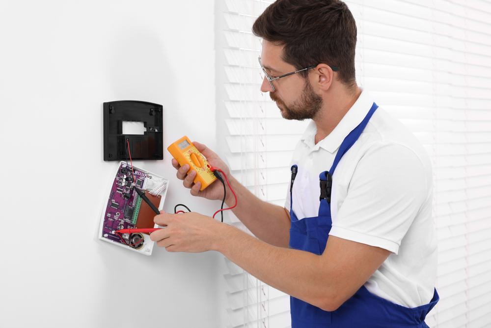
  • It’s Inexpensive

SDI cable is one of the most versatile and useful cables.

Professionals all over the world love it. Its ease of handling, reliability, and inexpensive nature add to the charm.

But no one is perfect, and SDI cable is no exception.

Though it can transmit a signal over long distances, it can’t compare to Fibre.

  • You save on costs

To compete with Fibre, you need repeaters and amplifiers.

It will significantly increase the cost. It has a lower bandwidth compared to HDMI.

And as of now, it can’t send a signal with a bit rate above 12Gbit/s.

However, what is the best selling point of SDI cables? It can alter video characteristics.

You can change the ISO or white balance in real-time.

Conclusion

You wouldn’t want your live baseball game to stream late due to video editing.

The broadcasting and TV industry uses SDI cables on a large scale.

They got popular during the 1980s and have become the go-to cables since then.

A new transmission medium, Fibre, has recently gained ground.

But it has a long way to go before disrupting the SDI foundation.

If you want a signal over the long-range at a friendly cost and good quality, SDI cables are the way to go.

With CLOOM Tech, your search for a good SDI cable manufacturer ends too.

Talk to us about how we can help you do more for less.

CCTV Cable: All You Need To Know How to Pick the Right Cable

CCTV camera setups can be costly if you don’t know which type of equipment you need.

Do you want to know how to choose a suitable CCTV cable without the help of any professional?

In this modern age, CCTV cameras have become the most crucial part of any security setup.

Whether discussing any residential building or military installation, CCTV cameras are necessary.

However, most people don’t know where to go when buying the right CCTV cameras, CCTV cables, and wiring harnesses for your facility.

Surveillance camera installed on the ceiling

Chapter 1: Types of CCTV Cable?

Most surveillance systems use CCTV cameras for security, as you can monitor your surroundings.

You can use the CCTV camera footage to analyze the exact situation if anything goes around you.

You can see what’s going around you and record the video for future reference.  

Technician installing CCTV camera for security

Wireless or Wired CCTV Camera

There are two types of CCTV cameras.

  • Wired CCTV cameras
  • Wireless CCTV cameras

Most small properties use wireless CCTV cameras, but wired CCTV cameras are still better than wireless cameras.

Wired CCTV cameras are less expensive than wireless CCTV cameras, and the video quality is also better than wireless cameras.

CCTV elements collection with security cameras electronic devices

Choosing the right cables for your camera setup if you are using wired CCTV cameras.

There are many types of cables that you can choose from.

Here are some types of CCTV cables. We have also discussed the pros and cons of each type.

1. Coaxial Cables

We use coaxial cables to transfer video, voice signals, and audio data in the internet and telecommunication fields.

We generally use these cables at home to connect DVD players and other media devices to our televisions and display devices.

TV and cable service providers also use these cables for the same purposes.

The best thing about this cable is the quality of the data transmission, as there is no loss of quality while transmitting data from one source to another.

Pros

The coaxial wires are durable and last for a longer time.

The cables are generally used in rough environments, and these coaxial cables are the best choice for harsh climate conditions.

The material in these cables is usually better than many other wires.

These cables can be used to deliver data and transmission for longer distances.

These cables don’t lose their quality even for longer distances.

The transmission quality of these cables is better than many other options we got here.

The video quality remains the same even after long-distance coverage.  

Cons

The only thing that can be stressful here is the cost of these wires.

Due to the high-quality transmission and quality materials, these wires are costly.  

2. Siamese Cable

These are just coaxial cables but with a power source.

If the power source is farther from the cameras, you can split the power cables from coaxial cables.

Pros

These cables are useable for transmitting data and power at the same time.

So, the usability of these wires is way better than standard transmission cables.

The video transmission in these wires remains unaffected due to the power supply. The data transmission is reliable for CCTV cameras.

As the power and data transmission is the same wire’s responsibility, setting up the cables is straightforward.

You don’t need to mix up things.

Cons

Compared to coaxial cables, these cables are complicated.

It would be best if you also had some technical knowledge to operate these cables for CCTV cameras.

3. Twisted-Pair Cables

These cables generally consist of two pairs of wires.

Pros

These cables are the best option if you don’t want any disturbance in your video transmission.

These cables reduce external interference in communication.  

The cables are better for safety as most users use underground options for these cables.

You can save a lot of space by using these cables.

Cons

Mostly, these cables are fragile, and you need to take care of these cables.  

4. Optical Fiber

Optical Fiber is the fastest way of data propagation.

These cables use glass coating or plastic sheets to transmit data at higher rates.

3d image of optical fiber cable for CCTV cameras

Pros

The data transmission rate for fiber optics is way higher than any other cable.

If your security setup needs faster data transmission, fiber optics is the right cable.

The data quality of fiber optics is also better than other cables.

These cables are capable of carrying high data for video transmission.

Cons

It would be best to install and maintain fiber optics with a great workforce.

The fiber optics installation process is way more complicated than any other cable installation.

These cables are more expensive than any other camera cables.

 CCTV Cable Connectors

To connect the CCTV cables to the display device, you need to use CCTV cable connectors, and you can use many connectors that suit your CCTV cable.

If you are looking for a connection between CCTV cameras and the display device, you must connect the CCTV cable.

Chapter 2: What is the CCTV Cable?

CCTV stands for closed circuit Television, and we use these cameras for security purposes in different locations around any property.

You can see the live footage of the surroundings on the screen in your room, and these cameras connect to the display devices with the help of CCTV cables.

Who does need a CCTV Cable?

All the security firms use CCTV cameras, which you can use for house security too.

Simply put, these cameras are useable everywhere you need to see the live footage around you.

These cameras are useable for all:

  • Offices
  • Buildings
  • Industries
  • Houses
  • Shops

Advantages of CCTV Cable

CCTV cameras will always be beneficial for your property and investment security.

Here are some main benefits of using CCTV cameras.

Crime Deterrent

You can avoid any possible theft by using CCTV cameras. You can see the live footage on your screen if something goes wrong around or within your property.

Monitor Live Footage

If you are running any business or office, you can use cameras to monitor the activities of your employees.

You can see what is happening around the office and how well your employees perform their duties.

Keep Records

You can store the footage of your cameras to keep a record of any activity.

If you have to use that information shortly, you can use the live footage from your cameras.

Chapter 3: Types of CCTV Cable

Many types of CCTV cameras are useable for different needs and scenarios. Some cameras are useful for close surveillance, and some offer long-range coverage of the surrounding.  

Here are some main types of CCTV cameras you need to know about to secure your properties and belongings better.

3d rendering security camera

Dome CCTV Camera

CCTV Cameras are most generally ideal for indoor security and reconnaissance applications.

Dome cameras get their name from the dome-molded lodging in which they sit.

The “dome” shape makes it hard to tell the course that these cameras are confronting and, in this manner, are perfect for preventing lawbreakers.

Speed Dome CCTV cameras enable the reconnaissance administrator to move the camera.

Bullet CCTV Cable

Bullet CCTV Cameras have a long, round, hollow, and decreased shape, like a “rifle bullet,” regularly ideal in applications requiring long separation seeing.

The camera isn’t intended to have skillet/tilt/zoom control yet; instead catches pictures from a fixed area, pointing at a specific zone.

Day/Night CCTV Cable

Day/night CCTV cameras have the unmistakable preferred position of working in ordinary and dreary situations.

These cameras don’t have Infrared illuminators because they can catch clear video pictures in fluctuating light conditions and obscurity.

Do all CCTV cameras need cables?

Do you need CCTV cables for all kinds of cameras or do we have some other options too?

You also have other options where you don’t need CCTV cables, as these cameras use wireless technologies like Bluetooth and Wifi.

If your Wifi is not operational, you don’t have access to your CCTV camera. Your property is at risk during that specific period.

So, it would be best to prefer wired CCTV cameras for better security and an economical solution for your security needs.

Always choose quality CCTV wires to avoid extra maintenance charges.

Chapter 4: Where to buy CCTV Cable?

In the previous chapters, we covered everything related to CCTV cameras and CCTV cables.

The first step is to choose the right CCTV camera and suitable CCTV cable type.

The next step is to choose the right platform for accessories.

You can buy cable buy cables and harnesses to install the cameras and cables from that platform.

Customized CCTV cables from CLOOM Tech with best quality material  

Can you get a custom CCTV cable from the electronic store?

Typical CCTV cables may not be suitable for special projects.  

You can use custom CCTV cables for individual product requirements for your installations.

Most of the time, stores and shops offer typical cables ideal for general use.

However, if you have special requirements and want customized cables for your CCTV cameras, you can contact CLOOM Tech. CLOOM Tech is a custom cable manufacturing firm.

Chapter 5: Custom CCTV cable from CLOOM Tech

CLOOM Tech can create custom cables for industries and households. In case of special cable assembly requirements, you can get everything as per your requirements from CLOOM Tech.

Why do you need a custom CCTV cable?

We use these CCTV cables in our offices, workplaces, and homes for several audio and video components.

CCTV cables are limited to individual use, but commercial sectors like telecommunication and the internet industry also use these cables for different purposes.  

If you have special needs and want to get customized CCTV cable, we can engineer the perfect customized CCTV cable for your setup.

We provide customized cable connectors, connecting cores, harnesses, cable assemblies, and shielding for home and commercial use.

What is CLOOM Tech?

CLOOM Tech is the top name for wiring harnesses and cable assemblies.

We offer customized manufacturing services for different sectors, including automobile, heavy, and commercial factories.

You are just a single click away from accessing the full range of services by CLOOM Tech.

Conclusion

No matter what kind of CCTV camera cables you need, we only provide CCTV cable assemblies.

We are offering other cable assemblies and harnesses manufacturing too.

All the products from CLOOM Tech are customizable per the users’ requirements.

If you hire an expert team to take care of everything regarding your project, CLOOM Tech is the name that you can trust.

If you have any queries related to our products and services, you can contact us, and we will try to get back to you as soon as possible.

The USB Extension Cable: How To Make Your Design

USB extension cables are of utmost importance in homes and workplaces.

It is almost impossible to discuss connectivity without the role of USB extension cables.

Are you always experiencing difficulties with data transmission?

I know how very discouraging it is for you. Irrespective of your challenges, there is an easy way to get good signal transmission.

It is possible to create a USB extension cable that suits your needs.

If you want to gain insight into how the USB extension cable works, this article is right; it unveils much importance, uses, and different ways of getting the right USB extension cable for your various needs.

The USB Extension Cable 1

Chapter 1: What is USB Extension Cable?

What is a USB extension cable?

The USB extension cable is a USB cable type that ensures the accurate transmission of signals and maintains proper quality.

The USB cable types remove the restriction that prevents the transmission of signals over short distances.

They also come in various colors, thicknesses, and lengths. The use of a USB extension depends on the user’s specifications.

Application of USB extension cable

The USB extension cable aids in the transmission of data. It also helps in charging mobile phones and electronic devices.

Furthermore, it makes using personal computers easily.

The USB Extension Cable 2

Chapter 2: Importance of The USB Extension Cable

The USB extension cable is of utmost importance in homes and offices.

Many connectivity needs are possible with the use of these cable types. Some of the significance of USB extension cables are:

It facilitates the transfer of data:

 Anyone conversant with a computer-related device understands the importance of proper signal transmission.

In cases where the signal is inadequate, it is a frustrating experience.

So many people settle for using software to facilitate data transmission speed.

There is no need to spend a vast sum of money purchasing software with a USB extension cable.

USB extension cable possesses a different quality that aids the transmission of files irrespective of size.

USB extension cables ensure the use of a portable device: Recently, many manufacturers have settled on manufacturing laptops and mobile devices that are easily moved around.

That is a result of the advent of USB extension cables.

The port of any electronic device is compatible with the USB extension cable.

You only need to consider the port size and if it suits the USB extension cable.

Multifunctional: 

The USB extension cable performs many functions almost at the same time.

It enables the user to connect many electronic devices and use them for multitasking.

It aids in the charging of devices: 

If you want to generate power for your mobile devices, the best cable type to go for is the USB extension cable.

The only criterion for using the USB extension cable for charging a mobile phone is to ensure that the port on the electronic device is compatible with the USB extension cable.

It can also generate electricity from your car, power bank, and other computer-related devices.

It is more reliable for charging mobile devices than the traditional charger type.

The transfers data without the aid of an internet connection.

The would help if you always use your mobile devices but cannot access the internet.

In such situations, the USB extension cables provide relief.

A typical example is transferring files on your mobile device.

How do you do it when you have urgent work on your mobile phone but no internet connection?

The answer is quite simple!

Attach your mobile phone to the computer system with a USB extension cable and transfer the files.

It curbs fluctuation associated with data transfer: It is common to experience fluctuation when transferring data.

However, there are ways to prevent the occurrence of such a situation.

That is especially common when you want to transfer huge files.

Most times, when you experience this fluctuation, it makes you uneasy because you have to start all over again! It is not a good feeling, and I guarantee you that.

Nonetheless, USB extension cables prevent such occurrences.

It also hastens the data transfer process while ensuring minimal error with transferring the data or information.

It is readily available: 

USB extension cables are virtually everywhere. It is easily accessible.

They are available in different supermarkets and other related-environment.

Interestingly, USB extension cables are affordable and easy to replace if necessary.

More so, it doesn’t require any problematic process of usage.

It comes in various forms:

 The USB extension cable is designed to meet your specification.

It comes in different types, colors, and sizes. Any kind you require is easy to create, depending on your preference.

If you prefer to move around freely while charging your phone, you must possess a long USB extension cable.

However, if it is for your power bank, which doesn’t require much space, you need a short one.

The USB extension cable is useful for creating efficiency in any activity.

Its relevance is second to none.

The USB Extension Cable 3

Chapter 3: Various Ways of Creating A Form of USB Extension Cable

Connecting the USB extension cables to get the best from your USB extension cable would be best.

The USB extension cables are notable for their length and ability to compensate for shorter distances.

Hence, it is very appropriate for you to understand how to improvise and achieve a USB extension cable in your different homes and offices.

There are four different methods of creating the USB extension cable.

There are always issues associated with shorter distances when using USB peripheral devices.

To prevent such problems, improvise, and create suitable USB extension cables.

The four methods of creating USB extension cables are:

How to extend the USB cable connection with a USB extension cable

Disassociate one end of the USB cable.

The USB cable end that you need to disconnect from your USB cable is the part that is attached to your computer system.

The name of the end of the USB cable device is known as the “A” connector.

Put the male end of the USB cable into the female end of the USB extension cable:

The male end of the USB cable works well with the female end of the USB connection cable.

The process’s third step requires connecting the extension cable’s male end to the furthest part.

It is important to emphasize that the male end part of both the standard USB cable and the extension cable is easily substituted for one another.

The USB extension is significant as they cover the barriers of short distances.

They are present in either single or multiple USB ports.

How to extend the USB extension cable with a USB extender

To get the steps correctly, you must identify the port on the end of the USB extender.

Connect the transmitter of the USB extender to a port on your computer system.

Place an Ethernet cable’s end to the transmitter’s other end on your USB extender.

The next step is effectively running the USB cable between the peripheral device you want to connect and the extender’s receiver.

Plug the end of the Ethernet cable into the receiver’s port.

The length of the USB extender depends on the length of the Ethernet cable in use.

It is known that Ethernet cables are more sufficient to transmit data to other cables.

They can transmit data with little interference or obstruction.

How to extend the USB connection with the aid of a USB over IP converter
Extending the USB cable connection using the USB over IP converter is possible.

There are two necessary steps to this. They are:

Remove one end of your USB cable from its port.

Put the disconnected part into the USB over the IP converter of your device.

The next step is to put the Ethernet cable into the Ethernet port on your USB over IP converter.

Put the other end of your cable into the port on your Ethernet cable.

It would help if you remembered that the USB IP converter is beneficial when using the USB device.

That is prevalent when you want to connect it to a network.

This is beneficial because it allows every other network to access data transmission easily.

The distance issue depends on the length of the Ethernet cable and the USB cable you want to use.

How to extend a USB connection with a wireless USB:

Place the wireless transmitter with a USB splitter cable. The USB splitter cable is multifunctional.

It aids a couple of peripheral devices to connect to a host computer system simultaneously.

To make this a reality, the peripheral devices need to be in close range or proximity.

The USB device needs to access the other devices easily. The USB device needs to be permissible to other devices.

That implies that the USB signal is to be readily accessible to other USB-related devices that require it.

The wireless USB network connection enables data transmission to other forms of multiple wireless devices at a close range with the network.

It also supports other devices within the wireless transmitter’s proximity.

Chapter 4: Where to Buy The USB Extension Cable

It is not just enough to get the required information. You also need to understand how to go about it.

Many people are caught up in a web of life that does not understand how to handle the extension cable.

It isn’t because they do not care, but a militating factor is an inability to get the right kind of help with the cable type.

Cloom Tech is an international service provider with many years in tech.

Seasoned professionals with vast experience and expertise adequately handle any activity or problem associated with the extension cable.

You do not have to be more concerned with getting your USB extension cables in one piece.

Whatever connection you require to achieve with the extension cable, rest assured that we are a set of trusted hands.

We deliver timely and accurate results within the shortest possible time frame.

Our organization is always eager to meet your needs and comfort your doorpost.

Conclusion

Extension cables are the most common cable type.

They are available in almost every home and office.

The uniqueness of the extension cable stems from the length and quality of service delivery.

There are methods of improvising to get your desired extension cable length.

So, contact us now!

You need to understand the different techniques, follow the easy steps, and have the desired result.

How to Protect your Projects with Custom Wiring Harness?

If you value your investment in any electrical project, a custom PCB Wiring Harness must be part of your safety measures.

Custom PCB wiring harnesses have always been very beneficial for projects where lengthy wiring has some involvement.

CLOOM Tech.Ltd can develop the custom PCB wiring harness for your projects to add a layer of protection and safety.

No matter what kind of project you are dealing with, harnessing the wire will always be advantageous.

Dealing with lengthy wire harnesses can be hectic, but a custom PCB wire harness can relieve pain.

PCB Wiring Harness 1

Chapter 1: What is the PCB Wiring Harness?

The wiring harness is an electric component’s systematic and organized wires bound.

It works as the power transmitter in electrical systems.

This process of bounding different wire harnesses includes various electronic tapes, straps, and wire lacing.

There is no specific rule for developing the wiring harness, but it depends on system requirements.

The design might differ for each project depending upon the application and design of the component.

PCB Wiring Harness 2

Suppose you have a complicated electrical project that requires professional custom PCB wiring harnesses,

CLOOM Tech.Ltd can develop perfect PCB wire harnesses for your project.

Our team focuses on providing customized wiring solutions by using the latest technologies.

Our custom wiring harnesses are part of several industries, and some of our main targeted sectors are:

  • Medical appliances
  • Telecommunication devices
  • Automotive industry
  • General electronic devices and military equipment

PCB Wiring Harness–Wire Harnesses to Protect Your Projects

A little damage to a wire harness in a big electrical project can cost you a fortune.

We cannot eliminate the risk but control the possible loss.

All the safety engineers and analysts recommend using wiring harnesses for the longevity and safety measures of the projects.


Chapter 2: Importance of the Wiring Harness to the PCB

Usually, the PCB harness seems to be an extra feature; it is an essential part of the whole project.

The benefits of a custom PCB wiring harness can improve the ROI and the maintenance cost.

Some of the given factors can clarify your vision about the importance of wiring harnesses to the PCB.


Wire Protection

Wires generally carry the data or work like the transmitter of energy.

In both cases, heat from the wiring and other damage can cause damage to the device or application.

In some cases, standard cables have also caused primary short circuits.

The wiring harnesses keep the wiring in an organized and protected manner.

This organization of wires not only provides better protection but also prevents the melting of the wires.

PCB Wiring Harness 3

Every wire in any electrical project is essential, and even a tiny cut on the smallest wire can lead to failure.

Do you want to spend hours troubleshooting the problem or spend some money on PCB wiring harnesses for preventive measures?


PCB Wiring Harness
Professional Appearance

When you showcase your work to the inspection team or the clients, the appearance of your components is the most important thing.

If your team works for an international firm, your work will be displayed to others.

Organized wires and components show your level of professionalism and make the learning process easier for the clients.

The professional appearance of the wires within a component builds a sense of trust and security in your client’s mind.

No one wants to hire an engineering team that will mess up their components and wires.

So, be professional and always invest in a custom PCB wiring harness for the better brand value of your work.


PCB Wiring Harness
Protection against any Injury

As we have already mentioned, even a few cuts in the wire coating can cause item damage and failure, which can also cause damage to your body.

The best way to conduct any troubleshooting process is to remove all the power sources, but some capacitors might give you an electrical shock.

When the developers organize the wires with PCB wire harnesses, you can easily access the targeted wires without damaging yourself.


Chapter 3: Other Ways the Wiring Harness Can Be Helpful

The basic and the most crucial purpose of the PCB wire harness is to protect the internal working of the components and the systems.

But the overall benefits of harnesses include the increased efficiency of the team and the technicians.

While working on the project, wiring harnesses can save much time and effort in dealing with lengthy wires.


Color Coordination

We develop custom PCB harnesses in different colors.

So while working on a big project, you can assign different colors to specific wires.

You can attach a red color harness to power cables and green color to data transfer wires.


PCB Wiring Harness
Isolating Connections to PCB

Many components require several wires for proper functionality; in such cases, the harness can make the job easier for the developer.

When the developers use the harness to isolate different wires, finding the right wire harness for the connection seems more comfortable.

Have you seen the connector in the USB cable that connects the USB to the motherboard?

We are talking about the same harness but at a more significant level.


Adding Style

If you want to add a touch of style and fashion to your project, colorful harnesses are your best choice.

These harnesses mostly work in computer chassis, where these wiring harnesses glow in different colors.


PCB Wiring Harness
Power Distribution Wires

Managing data-carrying wires seems more straightforward, but dealing with them is always risky when it comes to power cables.

When you know the exact working of each wire, you can easily maintain and repair the proper functionality of the project.


Chapter 4: Benefits of Custom PCB Wiring Harness

PCB wiring harnesses are available for all kinds of projects, but if you think your project is complicated and the general harness is not suitable.

You can get a custom PCB wiring harness from CLOOM Tech. Ltd.

Here are some further benefits of the wiring harness that can help you make the right decision for protecting your project and the investment.


PCB Wiring Harness
Preventing Damage from Heat

Electrical components and appliances can generate a vast amount of heat, and if you are dealing with high-energy wires, there are more chances of heat damage.

When all the components’ wires are well-organized, there are fewer chances of heat damage.

If heat causes the meltdown of the plastic coating, a wiring harness can prevent any possible short circuit.


Avoiding Direct Physical Damage

Adding an extra layer of protection to your project will always benefit the project.

Direct physical damage can occur due to any hardware tool, like a screwdriver.

The harness can keep the cost within the infected wires if something goes wrong with any particular wire.


Heat Dissipation

Most heavy-duty components generate heat; if your parts don’t have an exhaust fan, there must be a clear path for airflow.

The lengthy wires can block airflow, and the device may overheat the system.

Harnessing wires provide a bright and clean way for better airflow to avoid overheating problems.


Chapter 5: PCB Wiring Harness
Where to Customize the PCB Wire Harness

At CLOOM Tech.Ltd, We deal in all kinds of wiring harnesses, including power cables, signal cables, automobile harnessing cables, and heavy-duty industries.

Our team and R&D department always adopt new trends and technologies, so our customers always get the best solutions for their harnessing needs.

Contact our team if you are looking for an experienced team to develop custom PCB harnesses for your project.

We will analyze the plan to offer the best solution for your projects.


PCB Wiring Harness
Conclusion

Now, we have discussed everything regarding the custom PCB wiring harness. We have discussed that:

  • What is the PCB wiring harness?
  • Benefits of the wiring harness
  • Ways to protect your projects with a wiring harness?
  • How can it improve the efficiency of the project?

But the most important thing is to choose the right engineering team for the wiring harnesses at CLOOM Tech.

We are the top engineering firm with a certified complicated and custom wire harness development team.

We always ensure you get the best return on investment and more efficient results using our custom wiring harnesses.

Get A QUICK QUOTE

Fill in your details and we’ll get back to you in 24 Hours.

contact us

Get A QUICK QUOTE

Fill in your details and we’ll get back to you in 24 Hours.