Overheating in a circuit or faulty wire is the leading cause of many disasters. If you leave the wirings unchecked, you will be evacuating people from your building due to the fire that broke out. Loop impedance testing or loop testing might be a good investment option if you opt for preventive measures.
Conducting the earth loop impedance testing can ensure that your devices have enough current to operate during an electrical surge. To have the complete picture before you, we have this guide.
Get Your Free Sample!
Explore our custom services now. Email us at sales@wiringo.com for more details.
What is Earth Loop Impedance Testing?
A fault loop is a way the faulty current will follow if any fault arises between the phase conductor and the earth. Often, the wind is stuck into a loop because of the supply voltage with a high impedance; the higher the fault current, the more time the circuit breakers will take to operate.
Thus, you need to test every circuit to ensure no loop impedance drives the excess current in a loop. Also, you will check that if resistance does exist, it is not causing the current not to blow out the fuse. To explain, the loop test contains whether sufficient current passes through the protective devices such as fuse or circuit breakers. That way, you will ensure that fault currents are strong enough to operate the circuit breaker within a short period.
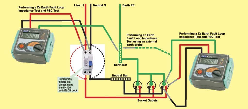
You will perform the test on the socket outlet and get loop impedance, excluding your installation type. For that, you have to complete the external earth fault impedance Ze and the highest Earth fault impedance Zs and the installation resistance.
Mostly, the electricians conduct the essential shock protection by connecting the earth connection with switches of indoor wiring circuits. This technique quickly cuts the supply to the neutral contact and exceeds the rugged voltage to an acceptable value.

Understanding Ground-fault Loop
Notice that in loop testing, the loop is not the same as the circuit. An electrical circuit is made on a specific design. In contrast, the coil may have elements where the current could find parallel paths to the ground.
For example, if any fault occurs in the distribution board, the current may travel through two paths. One from the grounding conductor, which backs to the supply transformer, and the other from the ground connector to the ground grid, leading into the soil.
In case of high impedance in the loop, the protective devices will become useless since they will not get enough current flow to become active. There is a chance that the fault current may be stuck into the loop, and the workers may get an electric shock from the faulty device. Hence, these parallel paths must have low internal impedance to allow enough circuit current to pass through the fuse.
Many electrical rules and regulatory bodies have some requirements without telling a specific procedure to conduct the test. Bodies as National Electric Code has Section 250-51, which narrates the grounding path to have less resistance to flow through excess current. Yet, you cannot fulfill the requirement unless you go through proper calculations such as unit or point-to-point methods.

Get Your Free Sample!
Explore our custom services now. Email us at sales@wiringo.com for more details.
Is Manual Testing an Easy job?
The mathematical calculations may be time-consuming. You also may not be a certified engineer, which makes you more open to mistakes. Additionally, it isn’t easy to consider the whole circuit length, all branches, and the connection to the transformer. Keep in the parallel paths you have already pointed out in the electrical circuits. All these factors make the accurate calculation almost a dream. Hence, you don’t waste time resolving the wire connection.
But, you cannot ignore the fact that these paths might significantly impact the total current of the system in the fault condition. Even the neutral conductors might start having high impedance in a larger circuit and may not activate protective devices although it has essential protection.
A simple solution to avoid these problems and errors is to implement an earth loop impedance test. With technologies emerging in the industry, you can take an exact loop impedance measurement. NEC Section 210-19 states, no voltage drop of more than 5% is acceptable in a loop due to impedance. There could be unsuspected parallel grounding, which increases the fault current in the distribution board and masks the voltage drop.
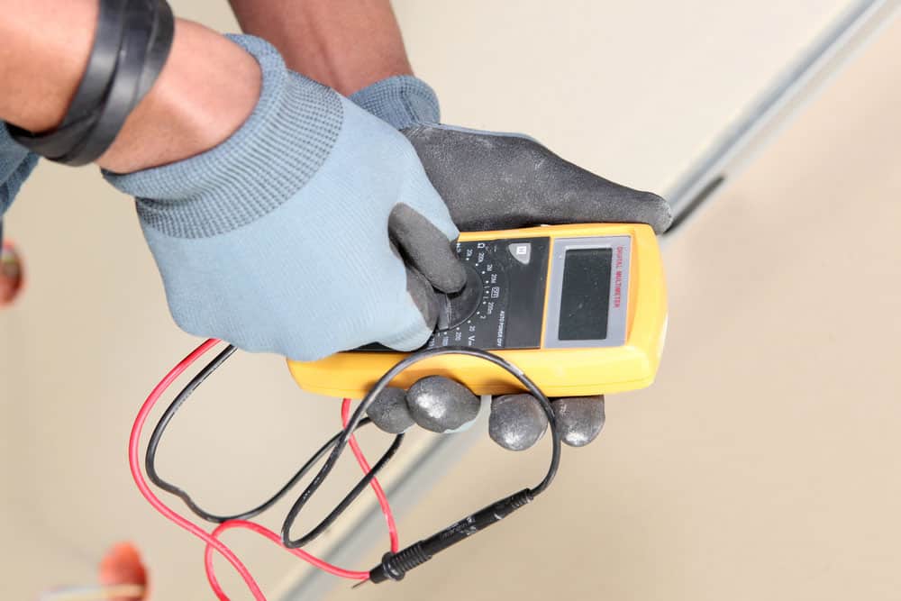
For that, you may need a loop tester, as it will provide you with accurate reading and actual circuit conditions, considering the temperature, lost currents, etc.

Loop Impedance Tester
Loop testers are a less consuming method, and the error rate in the reading of a faulty circuit is far less than other impedance testing methods. Within a few seconds, it will give you stable lessons assessing all the external factors as well.
The loop tester will simulate a fault from the live-to-earth connection or a neutral connection as a common practice. The tester will measure the unloaded voltage between conductors and provide some resistance in the link to prevent a fault. Then it will calculate the voltage drop across the resistor. Always remember that the supply voltage will be dependent upon the impedance of the loop.
Loop testers are one of the most preferred techniques due to their time-saving factors. Within two half-cycles, you can complete the test. Note that the duration of approximately 16 milliseconds is too fast. Even the protective devices cannot react in such a short time.
How to Conduct Earth Fault Loop Impedance Testing

Earth fault impedance is found by adding
- Transformer resistance (as of primary and secondary coils)
- Phase connection resistance
- Protective conductor resistance
- Source Ground resistance
- Installation resistance

External Earth Fault Loop Impedance Ze
While conducting the Ze fault loop testing, you will consider the supply of the entire circuit and the primary source of grounding. Remember that all the courses are isolated, and the main power supply is open. The external earth impedance measurement will confirm all the resistances except the installation earth resistance.
Before conducting the test, check that the main switch is off and no earth connections provide a parallel path. Following are the steps.
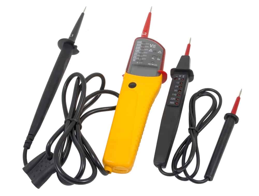
- Take an earth fault tester or choose the loop testing option on the multifunctional tester like Megger 1553. Test the supply side of the electrical circuit. Place the one test probe on the line terminal, the second on the neutral, and the third on the earth conductor.
- Now, press the button “Test” on the tester, and it will show a low reading ohm value on the screen.
- Record the value of Ze on the Electrical Installation Certificate.
Highest Earth Fault Loop Impedance Zs
On the other hand, you will test the highest earth impedance at the farthest point of each circuit. You will plug the loop tester into the socket-outlet or with an external earth probe for this test. The external earth probe then measures the impedance, and it measures either by touching the earth bar, conductive, or exposed metal parts of the equipment. Keep in mind that the process is hazardous and may lead to shock hazards.
You can find out the Highest Earth Fault Loop Impedance or Zs value for a circuit very conveniently once you have found the external loop impedance. The formula is simple, i.e.
Where
Zs = earth loop impedance of the circuit
Ze = earth loop impedance of the supply
R1 + R2 = Sum of resistance of Earth and Line
To conduct the test manually,
- Locate the points on the circuit that are far away for the test
- With an appropriate tester, place the probes on Line, neutral, and earth.
- Measure the values and write down the results.
Verification of Test Results
The value of the highest loop impedance should follow the fault impedance values that the designer has already given on the packaging and other standards. As a Rule of Thumb, the highest measured Zs should not be more than 0.8 times the relevant values per BS 7671 tables.
The BS 7671 prefers to calculate the highest impedance using the above method. But it may not be practical in real life, and hence you should test every circuit individually. The values may not be exact, but they can give you an idea in situations where a live wire test is dangerous.
Conclusion
As you conduct the test, remember to inspect all the minor changes that may point out the fault and occurring damages. Either, do not forget to reconnect the system to the ground before turning the main switch on. Here at Cloom, we offer custom wiring assembly with attention to each detail. To avail of our services, contact us now.
Hommer Zhao
Hommer Zhao serves as Director of Wiringo, leveraging a wealth of expertise in custom wire harness and cable assembly.
Drawing on more than a decade of hands-on expertise in the electronics field, Hommer focuses on wire harness manufacturing, custom cable assembly, and expedited restricted product production. His operations include a pair of wire harness production facilities and two dedicated PCB manufacturing & PCBA sites, all strategically located across Shijiazhuang, Shenzhen, Jiangmen, and the Philippines.
Hommer frequently refers to resources like Wiring Harness News for up-to-date insights and methods related to wire harness production.
Beyond his research and reading, Hommer also contributes to the Wiring Harness Manufacturer’s Association (WHMA), which offers invaluable resources and professional guidelines to wire harness specialists.
Get Your Free Sample!
Explore our custom services now. Email us at sales@wiringo.com for more details.


